Meta description: The difference between storefront and curtain wall shows up first in the drawing set. Learn how storefront, curtain wall, and window wall systems should be documented in permit drawings and BIM coordination to prevent RFIs, rebids, and glazing scope errors.
A familiar problem shows up late, usually when it's expensive.
The project has three glazing conditions. The drawing set treats all three the same way. Same wall type tag, same generic detail callout, same glazing spec language. The glazing subcontractor prices all of it as curtain wall, because that's the safest interpretation when the documents blur the system type. The number comes back high, the owner reacts, and the team starts walking backward through the set to explain that two of those conditions were meant to be storefront.
That rebid cycle is avoidable. It usually starts with production discipline, not design intent.
The difference between storefront and curtain wall matters long before submittals. It affects how the estimator reads the set, how the model gets built, how anchors are coordinated, and whether perimeter conditions can be detailed without patchwork RFIs. Window wall adds another layer of confusion because teams often label it as one of the other two and miss slab-edge requirements entirely.
Introduction
If a permit set treats storefront, curtain wall, and window wall as interchangeable, the bid package will expose the mistake.
That happens because glazing systems don't just look different in section. They carry different loads, drain water differently, meet structure differently, and require different permit-level documentation. When the drawings collapse those differences into one family, one note, or one detail, procurement gets distorted first. Field coordination and change orders follow.
For project architects and production teams, the primary task isn't defining glazing in abstract terms. It's making each system legible in the documents. A set should tell the estimator what is being priced, tell the reviewer what is being built, and tell the subcontractor where the critical interfaces are.
The comparison below is the baseline that should drive the rest of the set.
| System | Typical Use | Primary Support Condition | Water Management Logic | Drawing Risk if Misidentified |
|---|---|---|---|---|
| Storefront | Ground-floor and low-rise commercial frontage | Supported at base and head within a local opening | Drains to the sill | Under-detailed sill, wrong spec section, overpricing as curtain wall |
| Curtain wall | Multi-story façade areas | Anchored to structure at floor lines or structural points | Managed at each lite or intermediate horizontal member | Missing anchors, movement details, slab-edge interfaces, fire safing |
| Window wall | Slab-to-slab exterior infill | Bears on slab below and is laterally supported above | Depends on slab-to-slab interface strategy | Omitted head movement joint and fire safing |
Generic glazing details create specific coordination failures.
How Storefront Curtain Wall and Window Wall Systems Differ
Before the drawing set can be right, the team has to separate the systems correctly.
A storefront is generally a low-rise, ground-floor glazing assembly. One industry reference notes that storefronts are typically limited to about 10 to 12 feet in height, while curtain wall frames can reach at least 13 feet and are used on taller buildings, including projects above three stories, according to this glazing system comparison. That isn't just a span issue. It changes how the system performs and how the team should detail it.
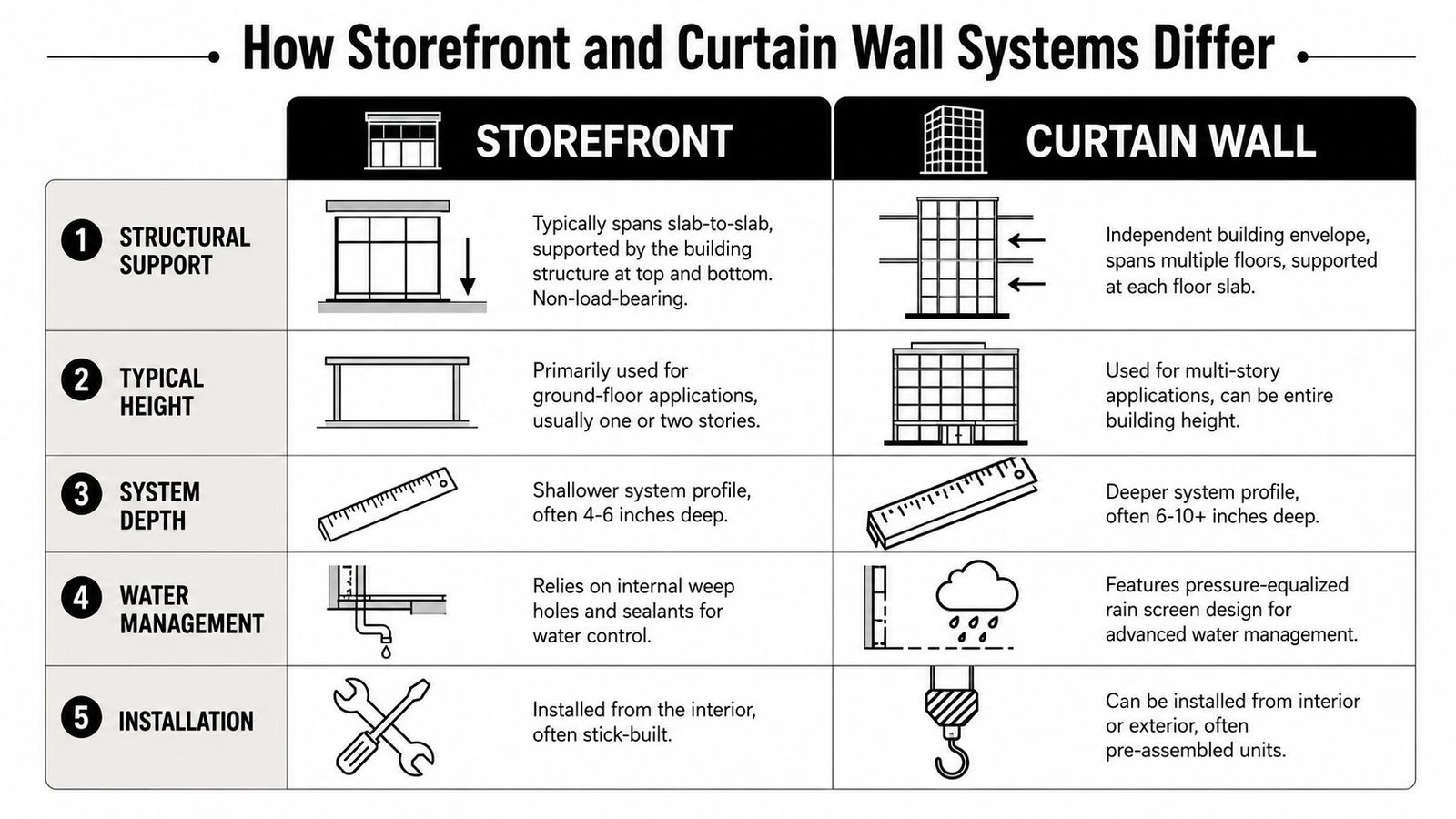
The structural distinction
Storefront systems are typically used at grade or in smaller commercial openings. They're supported within a local opening condition, usually at the slab below and the structure or soffit above. They aren't intended to act like a continuous multi-floor façade.
Curtain wall is a different category. It's engineered for multi-story façades and is anchored back to the structure as an independent exterior assembly. It's the right system when the façade has to span multiple levels and hold up under higher wind and weather exposure.
Window wall sits between the two in terms of confusion, not performance. It fills the opening from slab edge to slab edge. It bears on the slab below and is laterally supported at the slab above. It isn't a true curtain wall, but teams often document it as one because the elevation can look similar.
The documentation clue most teams miss
Water management gives away the system type fast. The same industry reference notes that storefront systems generally drain water at the sill, while curtain walls manage water at each lite or intermediate horizontal member through the assembly on larger elevations. If the detail package doesn't reflect that drainage logic, the set is already heading toward RFIs.
Geometry matters too. One industry source reports storefront mullions at around 2 inches, while curtain wall mullions are generally deeper at 2.5 inches or more, with curtain wall system depths reported from about 2.5 to 8 inches, as outlined in this discussion of façade system geometry and BIM implications. That affects section cuts, embeds, insulation continuity, and how you build families in Revit.
For teams building façade packages in Revit, the fastest way to lose control is to let one generic family stand in for all three conditions. A disciplined facade design workflow in BIM starts by separating system type before drafting a single enlarged detail. And if you're checking perimeter conditions for condensation risk, a practical primer on understanding thermal bridging is useful because frame depth and interface detailing directly affect thermal continuity.
Storefront System Drawing Requirements
Storefront is the system widely assumed to be simple. It isn't difficult, but it does punish sloppy documentation.
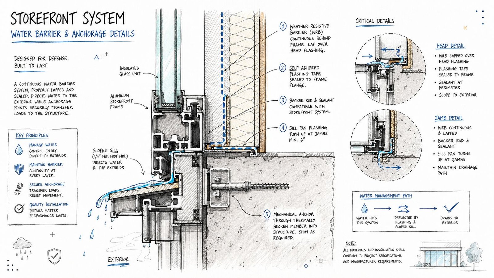
Start with a real elevation, not a diagram
A storefront elevation in the CD set should show the overall dimensions, framing module, mullion spacing, transom logic where applicable, and every operating element. If there's a glazed door inside that assembly, the elevation and the door schedule have to agree. Teams often coordinate the door schedule late and leave the storefront sheet carrying outdated panel widths or frame breaks.
That mistake creates shop drawing churn because the storefront vendor prices and lays out the system from the elevation, not from your internal assumptions.
A useful storefront elevation should identify:
- Overall width and height so no one has to infer system size from plan and section.
- Mullion pattern that matches the intended framing rhythm.
- Door and operable sash locations coordinated with hardware and schedule references.
- System designation that clearly separates storefront from curtain wall and window wall tags elsewhere in the set.
Head and sill details carry most of the risk
Storefront framing is anchored at the base and at the head. Both conditions need project-specific details. A copied manufacturer-style sketch without substrate context won't help permit review or field coordination.
The detail should show frame profile, anchor type, anchor spacing if known at permit level, adjacent construction, and continuity of air and water control layers. If the storefront hits a soffit, the soffit type matters. If it hits steel, that needs to be visible. If it lands on a curb or depressed slab, that belongs in section.
Practical rule: If the sill detail doesn't show where water goes, it isn't finished.
The sill is where production teams should slow down
Storefront systems generally drain to the sill. That means the sill condition can't be treated as a generic linework exercise. It should show the sill pan, weep holes, thermal break, and the relationship to adjacent finishes and waterproofing. In practice, the sill is where air and water problems appear first when the set is vague.
The schedule also matters. The glazing type, thickness, and performance values need to be assigned to the storefront condition in a way the subcontractor can price cleanly. If the schedule lumps storefront and curtain wall under one glazing note, the bidder will usually protect themselves, not your budget.
A disciplined storefront checklist in production review should ask three questions:
- Can estimating distinguish storefront from the other systems immediately?
- Can the installer see the drainage path at the sill without guessing?
- Can the permit reviewer identify the head, sill, and jamb conditions as system-specific details?
If the answer to any of those is no, the set isn't ready.
Curtain Wall Detail Permit Drawings
A permit set can look polished and still fail the project the moment the curtain wall subcontractor asks where the dead load lands, how drift is handled, or what closes the slab edge. Those are not shop drawing problems. They are permit drawing problems, and they drive RFIs, redesign time, and bid spread.
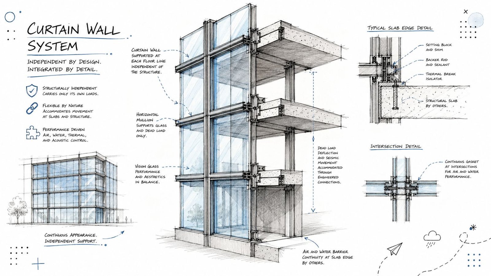
The elevation has to align with structure
Curtain wall needs a full-system elevation that does more than show pattern. It has to establish the grid, module dimensions, stack joints, panel types, operable units, and floor-line relationship in a way the structural team and façade bidder can both use.
On coordinated projects, I want the curtain wall elevation checked against the structural model before permit issue. If slab edges, embeds, or support steel do not line up with the mullion logic, the problem will surface later as revised anchors, added steel, shifted joints, and delayed shop drawings. A clean-looking elevation is not enough.
The best sets also tie detail callouts back to a clear system map. That is where curtain wall architecture production guidance becomes useful. The value is not the visual study. The value is linking each façade zone to real support conditions and a documented load path.
Anchors and movement need project-specific details
Curtain wall permit drawings should show how gravity load is supported, how lateral load is transferred, and where movement is allowed. Generic notes do not carry that information well enough for pricing or review.
Each anchor family should identify:
- Structural attachment location, such as slab edge, spandrel beam, tube steel, or embed plate
- Dead load support point so the installer and engineer are not inferring it from a typical section
- Drift and thermal movement allowance at heads, stack joints, and slab-to-frame connections
- Relation to air barrier, insulation, and waterproofing at each support condition
One typical anchor detail rarely covers the job. Corners, offsets, recessed slabs, canopies, and hung conditions change the connection geometry and often the tolerance strategy with it.
Interface details are where coordination either holds or breaks
Curtain wall touches more assemblies than storefront, and the permit set has to acknowledge that. Roof edges, parapets, opaque walls, expansion joints, sunshade attachments, podium transitions, and base-of-wall conditions all need real project-edited details.
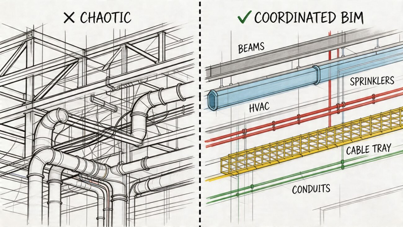
This is also where BIM coordination pays for itself. If the architectural detail says the air barrier runs behind the slab edge cover, the wall section, envelope details, and consultant models need to agree. If they do not, the conflict gets discovered during submittals or in the field, usually after fabrication assumptions have already been made.
Head, jamb, sill, and stack-joint details should show waterproofing continuity, insulation continuity, and closure materials at the level needed for permit review and trade pricing. Draw the condition the way it will be built.
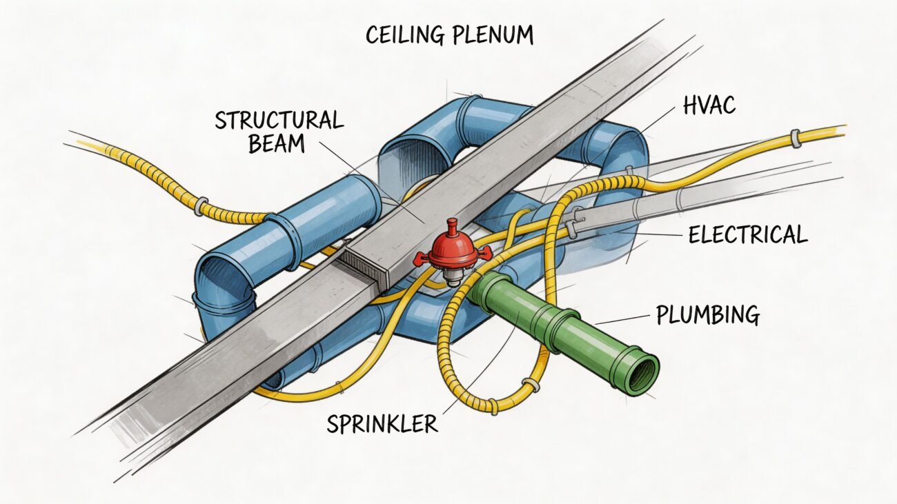
Fire safing has to be assigned, located, and visible
At each floor line, the slab-edge cavity behind curtain wall needs a fire containment detail. Leaving it to deferred submittals creates permit comments and scope gaps between the glazing, firestopping, drywall, and perimeter insulation trades.
The drawing set should show the location of the safing, the adjacent materials, and the relationship to the spandrel zone and interior closure. If multiple glazing systems are on the same project, label the curtain wall fire safing details so nobody confuses them with storefront conditions. That one clarification can prevent a surprising amount of rework.
Window Wall Construction Documents
Window wall is where many drawing sets go off course.
The elevation can resemble curtain wall. The framing can get labeled as storefront by a rushed production team. Neither label is reliable unless the slab-to-slab relationship is documented clearly. Window wall fills the opening between floor slabs, so the set has to show that the system bears on the slab below and is laterally supported at the slab above.
Slab edge conditions define the system
A window wall drawing package should make the slab edge explicit. If the system bears directly on concrete, show that. If it sits on a steel angle or a recessed pocket, show that instead. The detail should identify the support condition without forcing the bidder to infer it from structural sheets.
That matters because the slab edge drives more than anchorage. It affects insulation continuity, interior closure, perimeter fire containment, and tolerance strategy. A vague head and sill pair won't carry enough information.
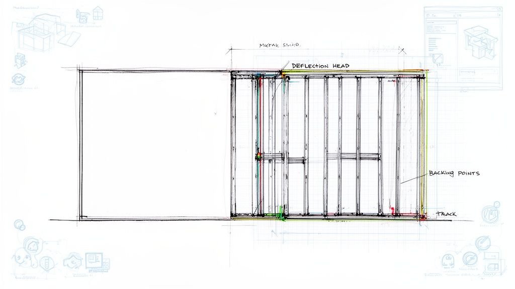
The head detail has to allow movement
The most frequent window wall error is a head condition drawn too tight. The slab above will deflect under load, and the frame isn't supposed to absorb that movement. The head detail needs a movement joint or slip condition that allows the slab to move without loading the glazing frame.
When teams misidentify a window wall as storefront, that requirement often disappears. The detail package then shows a neat, rigid head condition that looks coordinated on paper and creates trouble later.
Fire safing is not optional here either
Window wall also creates a cavity at the slab edge. That means the set should show fire safing at each floor line in the head and sill logic where appropriate to the system configuration. This detail is often omitted because someone thought “it's basically storefront.” It isn't.
A clean window wall package usually includes:
- System elevation with slab-to-slab relationship visible
- Base support detail showing actual bearing condition
- Head movement detail that accommodates slab deflection
- Fire safing detail tied to slab edge condition
- Schedule references that separate window wall from storefront and curtain wall types
If those aren't explicit, expect RFIs during shop drawing review.
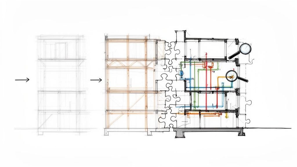
Coordinating Glazing Systems with Other Disciplines
Even a clean glazing sheet set can fail if the interfaces aren't coordinated with structure, MEP, and fire protection.
Neutral industry guidance notes that curtain walls weep each lite individually, while storefront systems generally drain the whole elevation to the sill. That difference becomes critical at slab edges, corners, and transitions to adjacent systems, as discussed in this article on curtain wall and storefront perimeter coordination. In practice, BIM teams don't get into trouble because they forgot the label. They get into trouble because the drainage path breaks at the interface.
Structural coordination has to happen before details are frozen
The structural engineer needs enough information to verify anchors, support conditions, and transferred loads. That doesn't mean architecture has to complete delegated design. It does mean the set must show where the system lands and how it intends to connect.
If the model places curtain wall anchors at locations the slab edge can't support, that issue should be visible during coordination, not after glazing procurement starts. The same goes for window wall bearing conditions and storefront head supports tied to light-gauge framing or soffit construction that can't perform as drawn.
A disciplined review checks the following early:
- Anchor locations against slab edges, beams, and framing lines
- Tolerance conflicts between façade geometry and structural offsets
- Spandrel zones that need closure, insulation, or fire protection coordination
- Transition points where one glazing system shifts to another
MEP coordination usually fails at the perimeter
Perimeter heating, fan coil units, receptacles, shades, and access panels all compete for the same strip of building. The glazing sill detail is where those conflicts surface.
If a perimeter unit heater crowds the sill pan or blocks maintenance access, the detail is wrong. If electrical rough-in crosses a thermal break or interrupts a drainage zone, the model isn't coordinated. These aren't theoretical coordination issues. They are common reasons RFIs appear after interior partitions are already underway.
For teams dealing with glazing interfaces and envelope components together, window glazing and glass coordination in BIM works best when the perimeter zone is modeled as an interface problem, not as separate trade objects dropped next to each other. And while it serves a residential audience, this guide for Phoenix homeowners on door projects is a useful reminder that opening modifications always affect adjacent framing, weather protection, and finishing scope. The same coordination logic applies on commercial perimeter changes.
The façade doesn't fail in the middle of the glass. It fails where teams hand responsibility to each other.
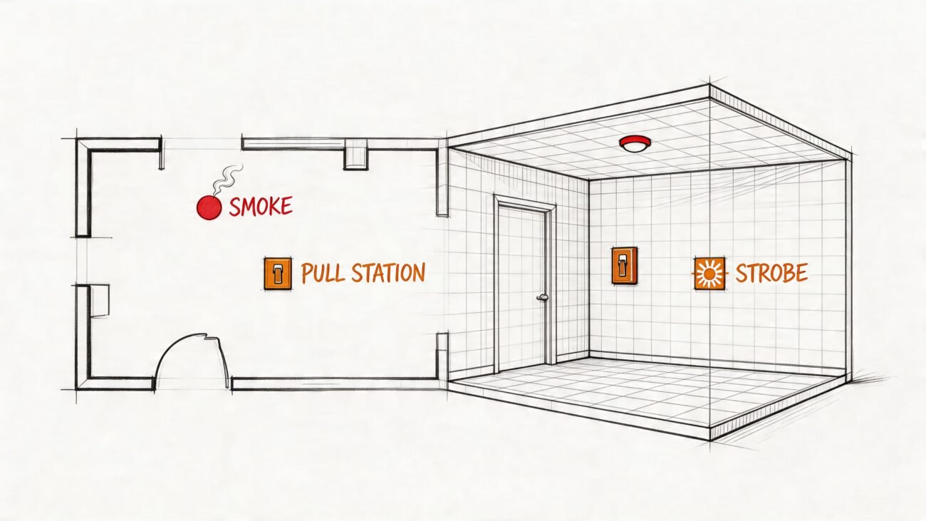
Fire protection has to see the frame, not just the room
Sprinkler coverage at the perimeter can get distorted by deep mullions, soffits, interior fins, and shade pockets. If the fire protection layout is produced without reference to the glazing model, the field team may end up relocating heads late.
That's avoidable when the BIM model carries enough fidelity at the perimeter for clash review and code-based spacing checks. On glazing-heavy projects, perimeter coordination meetings should include architecture, structure, MEP, and fire protection before the sheet set is locked.
Fixing Common Glazing System Drawing Deficiencies
The set looks complete at 90 percent CDs. Then the glazing sub asks where the curtain wall anchors land, interiors asks how the head closes at a soffit, and the fire protection designer flags the slab edge because no safing condition is shown. That is how glazing RFIs start. The issue is usually not the system itself. The issue is that the drawings, schedules, specs, and model do not describe the same assembly.
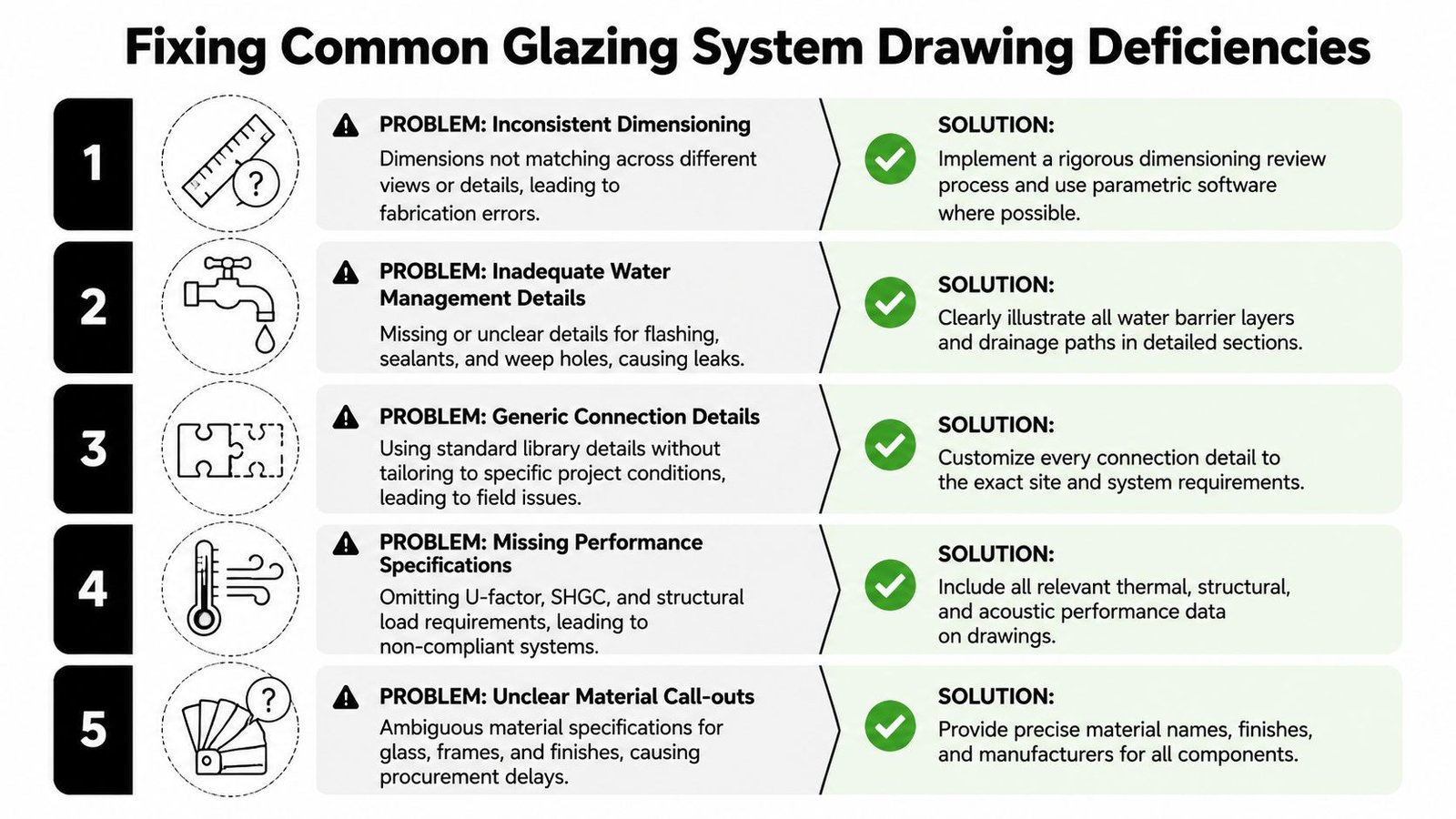
Stop using one detail for multiple systems
A shared head or sill detail across storefront, curtain wall, and window wall is a documentation error. Each system has different support assumptions, different movement behavior, and different perimeter conditions. If the sheet set treats them as interchangeable, the field team has to guess where the documents should have been specific.
The fix is straightforward. Every glazing tag should trace to a system-specific detail group, a schedule entry, and a matching specification reference. If that chain breaks anywhere, expect bid exclusions, substitution noise, and late clarification sketches.
Catch the omissions that trigger RFIs
The repeat failures are predictable:
- Curtain wall elevations without anchor logic at each floor or structure interface.
- Missing slab-edge safing details where curtain wall or window wall creates a rated perimeter joint.
- Storefront sills with no drainage path and no clear pan, weep, or thermal separation strategy.
- Window wall heads drawn tight to structure with no allowance for slab deflection or building movement.
- Schedules that mix system names or fail to distinguish storefront from curtain wall and window wall clearly.
- Spec and drawing conflicts where one document calls for curtain wall and another shows storefront framing.
These are drawing problems first. They become budget problems fast. The estimator carries qualifications, the glazing contractor sends RFIs, and the design team burns time answering questions that should have been settled before issue.
Build a QA pass around model-to-sheet agreement
A useful production review goes past, "Is there a detail on the sheet?" It checks whether the model, detail callouts, schedule language, and spec section all point to the same intended system. On façade-heavy jobs, I look for scope drift in three places first: type names in Revit, keynote language on details, and schedule descriptions. If those do not match, the submittal phase will expose it.
Use a short QA checklist:
- Is the glazing system named consistently in the model, schedule, details, and spec?
- Does the detail show the actual support condition and load path?
- Is the drainage and air-water barrier continuity clear at the interface?
- Is expected movement shown at heads, slab edges, and dissimilar connections?
- Is perimeter fire containment identified where the assembly creates a cavity?
- Can a bidder price the scope without making assumptions?
That review matters even more where exterior glazing connects to interior fit-out decisions. Teams working through tenant layouts, fronts, and partitions run into the same documentation issue. The intended use has to be stated clearly. This resource on planning glass for office spaces is a useful reminder that glass scope gets expensive when location, performance, and interface responsibilities stay vague.
A glazing package is ready when the architect, bidder, BIM coordinator, and field superintendent can all read the same scope from it. If they cannot, the missing coordination will show up later as RFIs, sketch revisions, and lost fee.