Meta description: Grounding and bonding requirements in commercial electrical CDs. What permit drawings must show for GES, EGCs, separately derived systems, and structural bonding to avoid plan check and final inspection failures.
The job looked clean on paper. Plan check cleared, rough-in moved forward, and everyone assumed the electrical package was in good shape. Then final inspection hit three issues at once. The inspector found that the grounding electrode system wasn't bonded to the building steel, one feeder had an undersized equipment grounding conductor, and a transformer classified as a separately derived system had no system bonding jumper shown on the one-line.
Those aren't punch list details. They're drawing failures.
All three are NEC-driven requirements that should have been documented in the permit set before the first conduit run. When they're missing, the field team improvises, the inspector asks for a design basis that isn't on the sheets, and the project pays for it in rework, RFIs, and schedule drag. That's exactly where margin starts leaking.
For commercial permit work, bonding and grounding need the same production discipline as feeder sizing, panel schedules, and fault current coordination. The drawings must show what gets connected, where it connects, and how the path is established for each system type. If the set stays vague, the review stays unpredictable.
Introduction
The most frustrating inspection failures are the ones that arrive late. The service is energized, panels are labeled, equipment is in place, and the team expects a routine closeout. Then the inspector flags missing grounding and bonding documentation that should have been embedded in the permit drawings from day one.
A common pattern shows up repeatedly in commercial work. The grounding electrode system isn't bonded to building steel. An equipment grounding conductor is too small for a feeder. A transformer doesn't show the required system bonding jumper on the one-line. Each item points to the same root problem. The set documented distribution equipment, but it didn't fully document the safety path that supports fault clearing and code compliance.
That gap matters because the reviewer and the inspector don't evaluate intent. They evaluate what's shown.
For commercial electrical CDs, the question isn't whether the contractor knows Article 250. The question is whether the permit drawings clearly establish the required grounding and bonding design for the building, the feeders, the structural frame, and every separately derived system.
Why Grounding and Bonding Are Under-Documented
Grounding and bonding are life-safety systems. They protect people from shock exposure and protect equipment by giving fault current a reliable path. Yet in many permit sets, they're still treated like field means and methods.
The workflow problem is easy to recognize. The engineer sizes the service, feeder conductors, overcurrent devices, and panelboards. The one-line gets attention. The schedules get attention. Then grounding and bonding collapse into generic notes such as “install per NEC.” That note doesn't carry a design.
The design gap that causes inspection trouble
Bonding and grounding aren't interchangeable functions. The technical distinction matters in the CDs because the drawings must show both intent and path. As GT Engineering's grounding and bonding guidance explains, bonding establishes electrical continuity between equipment to prevent potential differences that cause shock, while grounding provides the reference point to the earth. The same source notes that a low-impedance bonding path is a functional requirement so protective devices operate instantaneously during a fault.
If that path isn't explicit on the drawings, the field has to infer it.
That's where commercial teams get exposed. The permit reviewer is checking compliance, but the set doesn't show the grounding electrode system, the bonding jumper locations, or the equipment grounding conductor sizes. The inspector is left verifying an installation without a complete documented basis.
Practical rule: If the drawings don't identify the bonding and grounding path, the contractor is designing in the field.
Why complex buildings make this worse
This gets more serious in buildings with multiple services, generators, transformers, transfer schemes, telecom rooms, and structural steel spread across several levels. Those aren't simple “rod and wire” conditions. They're coordination problems across architectural, structural, electrical, and specialty scopes.
A mature production team treats grounding and bonding as part of permit readiness, not as an afterthought after the one-line is done. That means building QA checks around the same things reviewers will ask for on commercial permit drawings:
- Service-level documentation that identifies the grounding electrode system and its connection path
- Feeder-level documentation that shows the equipment grounding conductor or qualifying metallic raceway strategy
- System-level documentation for separately derived sources, bonding jumpers, and electrode connections
- Coordination-level documentation tying electrical grounding to structural steel and lightning protection scope
What works is simple. Show the path. Show the size. Show the connection point. Anything less invites correction comments.
Documenting the Grounding Electrode System
NEC Article 250 Part III drives the grounding electrode system, and the drawings need to treat it as a documented network, not a note in the general requirements. For commercial work, the permit set should show how the building uses all available grounding electrodes present at the site.
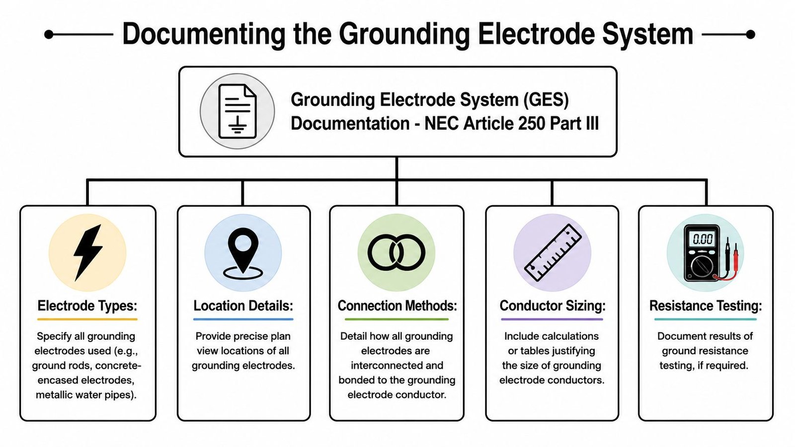
What must appear on the drawings
At minimum, the set should identify the electrode types being used and where they connect into the grounding electrode conductor path. That includes concrete-encased electrodes, rod and pipe electrodes, ground rings, and building steel where present and connected.
For the concrete-encased electrode, the permit set shouldn't stop at a note calling for a Ufer. Show the connection point and route it back to the service equipment or designated grounding electrode conductor point. The production issue here is coordination. If the structural and foundation sheets don't align with the electrical intent, the installer guesses or waits for an RFI.
A concrete-encased electrode needs to be documented with enough precision to be buildable. The article brief for this set requires the detail that it consists of a minimum 20 feet of reinforcing steel or bare copper conductor encased in foundation concrete. If that condition is part of the design basis, put it on the sheets where the field can use it.
Building steel and ground ring details
If the building uses structural steel as part of the grounding electrode system, the electrical drawings should show the actual bonding location on the steel. “Bond building steel” as a note by itself isn't enough. Identify the column or grid location, show the conductor route, and coordinate the connection method with the structural set.
If a ground ring is part of the design, the site plan or electrical site plan should show:
- Ring location around the building or served area
- Conductor size as designed
- Burial depth as required by the design documents
- Connection points back to the grounding electrode conductor system
Where site conditions force nonstandard installation, the drawing set needs to be explicit. This practical overview of electrical earth ground safety is useful because it reinforces a field reality many permit sets skip. Earth connection details aren't abstract theory. Material choice, burial conditions, continuity, and inspection access all affect whether the installation performs as intended.
Show the grounding electrode system on a dedicated diagram or on the service plan. If the reviewer has to reconstruct it from scattered notes, the set isn't ready.
There's another issue teams miss during site-driven redesign. NEC 2023 permits horizontal burial of grounding electrodes in trenches when vertical installation is impossible due to rock, but it does not provide guidance on corrosion mitigation strategies for long-term resilience in high-resistance soils, as noted in this NEC 2023 grounding discussion. If that condition exists, the drawings should document the chosen approach clearly because the code path alone doesn't resolve durability questions.
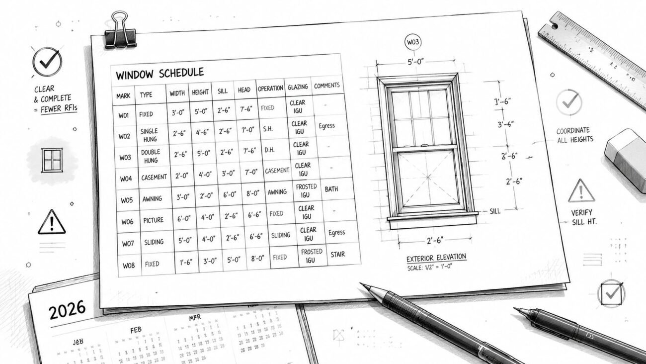
Specifying Equipment Grounding Conductors
A conduit and conductor schedule that lists phase conductors and neutrals but leaves out the equipment grounding conductor is incomplete. Reviewers see that immediately. Inspectors see it later, and by then the fix is expensive.
For permit drawings, every feeder and branch circuit that requires a wire-type equipment grounding conductor should show the EGC size directly in the schedule. Don't force the field to infer it. Don't hide it in a standard note. Put it where the installer, reviewer, and QA lead expect to see it.
Schedule discipline matters
The production rule is straightforward. Size the equipment grounding conductor by NEC Table 250.122 and show it in every applicable conduit and conductor schedule. If a schedule omits that column, it creates uncertainty for estimating, routing, and inspection.
That omission causes downstream problems fast:
| Drawing issue | What happens in the field |
|---|---|
| EGC size omitted | Installer makes an assumption or asks for an RFI |
| EGC shown generically | Conduit fill may no longer match the actual pull |
| Feeder revised late | EGC may no longer match the overcurrent device |
The avoidable mistake is treating the EGC as secondary because it's not a phase conductor. In real projects, it affects conduit sizing, pull box sizing, wireway space, and final compliance.
Raceway strategy must be explicit
If the design relies on a wire-type EGC in raceway, show it as a conductor. If the design relies on the metallic raceway itself as the equipment grounding conductor, the drawings need to say so clearly and confirm that the raceway type qualifies under NEC 250.118.
That's not a drafting preference. It's a documentation requirement.
I've seen feeder schedules where one area of the set assumes a copper EGC and another area assumes the conduit is the grounding path. That inconsistency doesn't fail gracefully. It creates mismatched takeoff, field confusion, and inspection friction because no one can tell what the engineered intent was.
Large feeders change the coordination problem
Large feeders deserve their own QA checkpoint. The required equipment grounding conductor can be substantial, and if the conduit size was picked using only phase and neutral conductors, the installation may no longer fit as drawn.
Before issue, confirm three things:
- OCPD alignment so the EGC matches the protected circuit
- Conduit fill so the raceway shown can accommodate the full conductor set
- Revision control so feeder changes trigger EGC review, not just phase conductor review
That last one gets missed constantly in fast-paced CD production. Teams update load data and breaker size, but no one revisits the grounding conductor.
A second misconception shows up in more advanced facilities. Code-compliant bonding jumpers do not automatically guarantee fault-clearing speed. In facilities with distributed energy resources, high-frequency impedance shifts can delay breaker tripping, and 38% of such industrial facilities experienced delayed fault clearing despite compliant bonding, according to the cited material in this Mike Holt reference PDF. For commercial teams working around DER scope, that's a reminder to coordinate the grounding and bonding strategy with the actual system architecture, not just minimum code language.
For feeder design coordination, this belongs in the same review pass as electrical load calculations. The grounding path isn't separate from production logic. It affects the same conduit schedules, risers, and equipment connections.
Detailing Separately Derived Systems
Separately derived systems fail inspection because they're often drawn halfway. The transformer is on the one-line. The secondary conductors are shown. The disconnect is shown. Then the critical bonding and grounding information is missing.
That's where the field starts guessing.
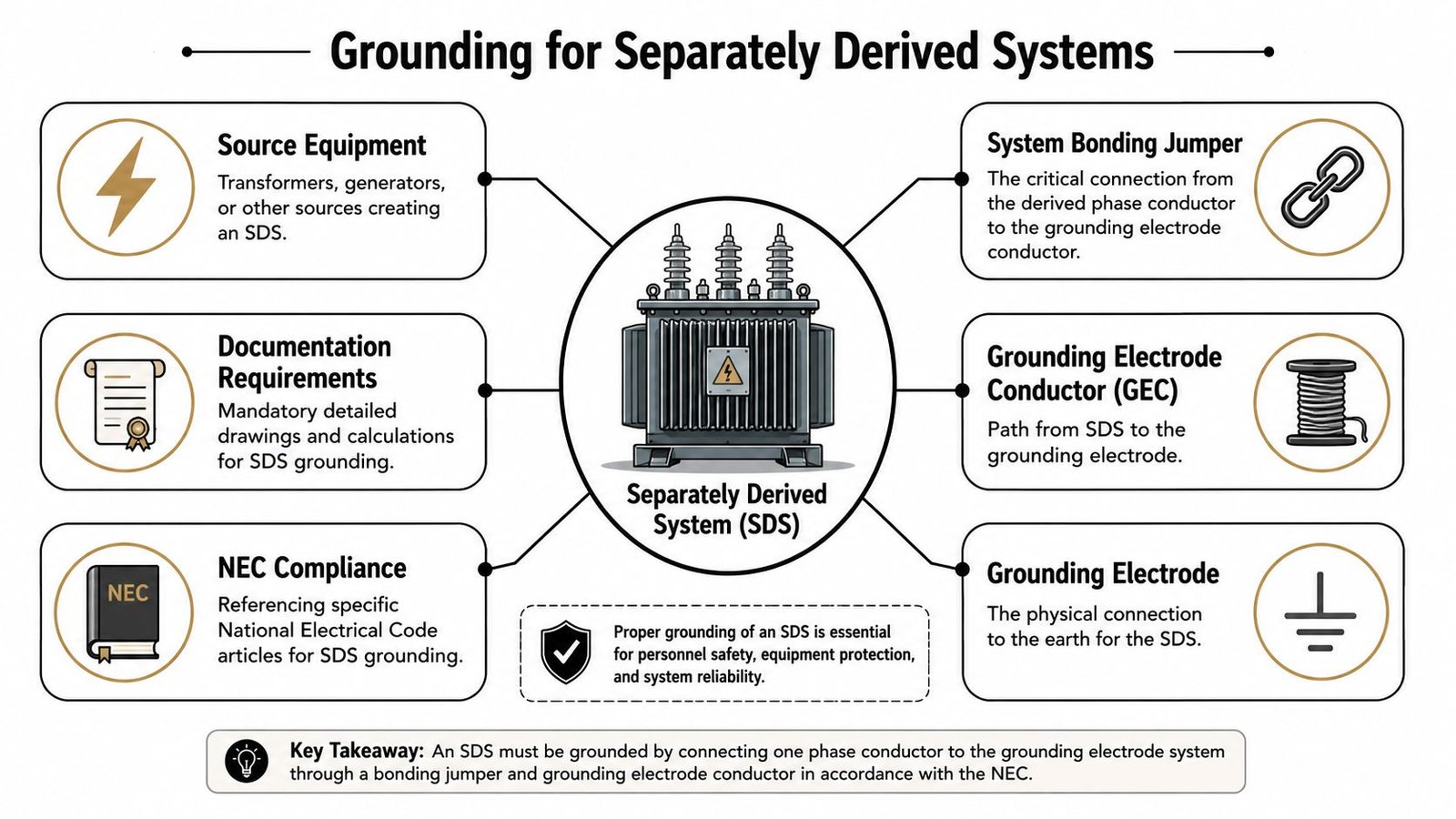
What the one-line must include
For a separately derived system such as a transformer, a generator with a transfer arrangement that switches the neutral, or certain UPS configurations, the one-line must show the system bonding jumper. The article requirement here is direct: NEC 250.30 requires a system bonding jumper for separately derived systems, and it must be shown on the one-line and sized per NEC 250.102.
If it isn't shown, the permit set leaves the source bonding method unresolved.
That omission causes a chain reaction. Shop drawings become interpretive. Installers pick a location without a clear design basis. Inspectors ask where the neutral-to-ground bond occurs for the derived system, and no sheet answers the question cleanly.
Grounding electrode connection for the derived source
The drawings also need to show the grounding electrode conductor from the separately derived system to the nearest available grounding electrode, with the conductor size and intended route identified.
That routing matters in commercial interiors because the transformer location may be remote from the main service equipment. If the path isn't documented, the contractor may route it inefficiently, route it inconsistently with the design, or miss the connection entirely until inspection.
A useful comparison point comes from telecom work, where standards are often tighter than general electrical practice. In telecommunications infrastructure, ground resistance shall not exceed 2 ohms, and the bonding conductor must be a minimum 6 AWG green-insulated copper connected via exothermic welding or listed two-hole compression lugs, per this telecommunications grounding and bonding standard summary-1108.pdf). The lesson for commercial electrical CDs is practical. Sensitive systems don't tolerate vague grounding details, and neither do inspectors reviewing derived systems.
Draw separately derived systems as complete sources. If the one-line shows only power flow and not bonding flow, it's unfinished.
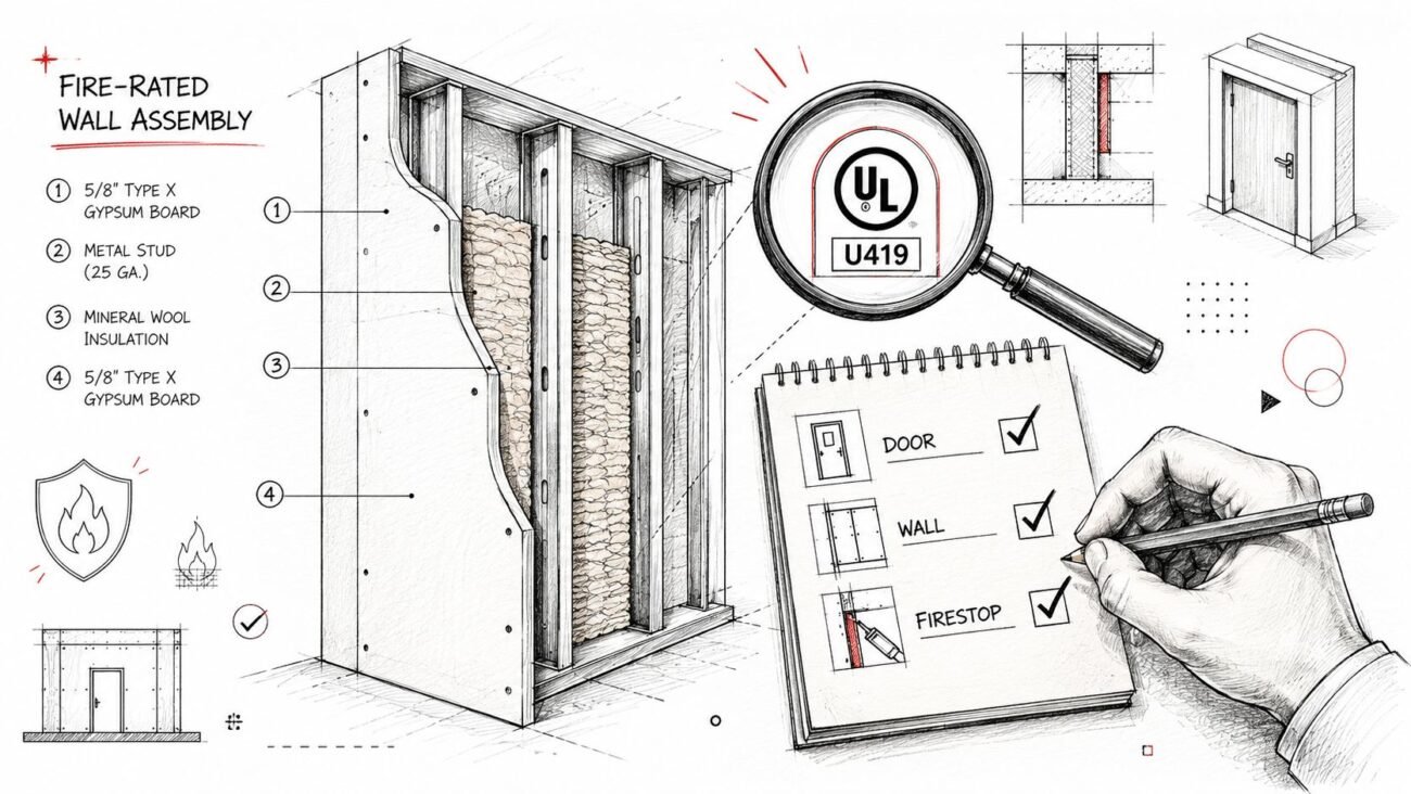
Showing Structural and System Bonding
Structural steel bonding is one of the most common blind spots in commercial electrical CDs because the responsibility gets blurred between electrical, structural, and specialty consultants. The code issue doesn't care whose scope box it lands in. If the structural metal is likely to become energized, the bonding requirement still exists.
The electrical set has to show it.
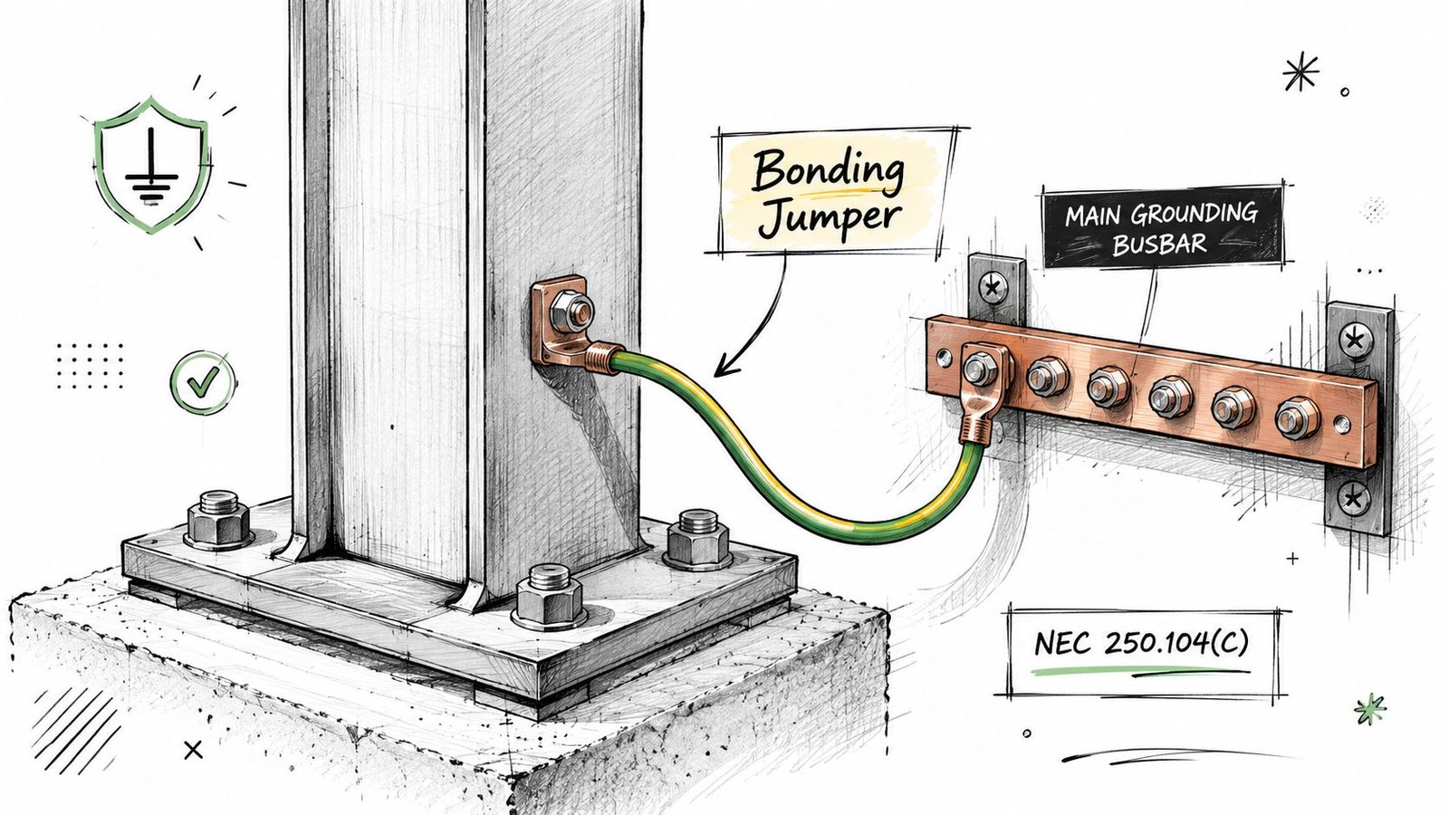
Structural steel needs a visible connection point
For commercial buildings with a steel frame, the drawings should identify the bonding conductor connection point on the structural steel and show how it ties back to the grounding electrode system. A note that says “bond structural steel where required” doesn't provide enough installation direction for a permit set.
BIM workflow discipline pays off. If the model and drawing templates force a connection point callout, conductor note, and detail reference, the omission rate drops. If the team relies on memory, someone always assumes another sheet handled it.
A strong production checklist for this item includes:
- Grid-based location for the steel bonding connection
- Conductor identification tied to the electrical detail set
- Detail reference showing the intended bond path back to the grounding system
- Scope note clarifying who furnishes and who installs the connection hardware where required by project delivery method
Lightning protection coordination can't stay off-sheet
If the project includes a lightning protection system, the electrical grounding electrode system and the lightning protection grounding need a documented bonding connection. This is frequently designed by a separate contractor, but the electrical set should still show the required bonding connection point at minimum.
That single coordination note prevents a familiar closeout problem. The lightning protection installer assumes the electrical contractor will provide the bond. The electrical contractor assumes the lightning protection scope includes it. Nobody draws it. The inspector asks for it at the end.
Bonding and grounding for flammable liquid handling systems show why connection continuity has to be explicit, not assumed. For containers of Category 1, 2, or 3 flammable liquids with a flashpoint below 100°F (37.8°C), grounding and bonding are mandatory under the cited guidance, and bonding cables with confirmed resistance of 1 megohm or less are used to validate circuit integrity, as outlined in this grounding and bonding fact sheet. The broader takeaway for commercial drawing production is simple. Safety-critical bonding paths must be shown as engineered connections, not left to assumption.
A Checklist for Plan Check and Inspection
Before issuing for permit or construction, run a dedicated grounding and bonding QA pass. Don't bury it inside a general electrical redline review. It needs its own checkpoint because the failures are usually omissions, not calculation mistakes.
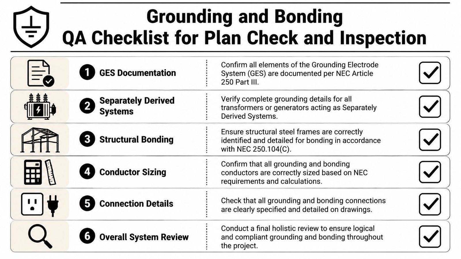
Pre-issue review items
Use a short production checklist that the engineer, BIM lead, or QA reviewer can verify sheet by sheet:
- Grounding electrode system shown: Add a GES diagram on the electrical site plan or service equipment plan if it's missing.
- Concrete-encased electrode routed: Show the CEE conductor route and connection point back to service grounding.
- EGC size column present: Every conduit and conductor schedule should include the equipment grounding conductor size where applicable.
- Separately derived systems complete: Each transformer or other derived source should show the system bonding jumper on the one-line.
- Derived system electrode path documented: Show the grounding electrode conductor from the source to the nearest available electrode.
- Structural steel bonding identified: Add bonding location, conductor size, and detail reference on the electrical sheets.
- Lightning protection bond coordinated: Show the required connection point even if the lightning protection design is delegated.
What teams often miss in practice
Most failed reviews aren't caused by not knowing the code. They're caused by production inconsistency.
One office standard omits EGCs from schedules. Another team puts grounding notes only on the one-line. Structural bonding is mentioned in keynote legends but never placed on plan. The transformer detail exists in one project template but not another. That's how avoidable corrections become repeatable.
A useful discipline is to align this review with broader permit-readiness QA, similar to a commercial building inspection checklist. Grounding and bonding shouldn't be an isolated technical exercise. They should be part of the same repeatable release process that checks life safety coordination, equipment access, labeling, and discipline interface points.
For teams that work across jurisdictions, local code context also matters because permit culture changes the level of scrutiny. Even when you're focused on commercial work, a straightforward code-reference example such as residential building regulations in Tennessee is a reminder that reviewers expect documentation that is explicit, jurisdiction-aware, and easy to verify. Commercial electrical CDs need that same clarity.
Missing grounding and bonding information rarely stays a paperwork problem. It turns into field redesign.
Conclusion
Good bonding and grounding documentation doesn't mean adding more boilerplate notes. It means putting design intent directly on the drawings so the permit reviewer, installer, and inspector can all follow the same path without guesswork.
That's what predictable delivery looks like in commercial electrical production. Show the grounding electrode system. Show the equipment grounding conductor sizes. Show the system bonding jumper for every separately derived source. Show the structural and specialty bonding interfaces. When those items are documented with discipline, RFIs drop, inspections go smoother, and project margin stays protected.
If your team wants stronger permit sets, tighter QA, and more reliable electrical documentation workflows, contact BIM Heroes for MEP production support and review the MEP services resources built around checklists, templates, and production-ready delivery systems.