Meta description: Panelized roof systems save time on site only when the BIM model is resolved before fabrication. Learn the coordination workflow that prevents bearing, connection, and MEP penetration errors.
The truck is unloaded, the crane is booked, and the first roof section is ready to fly. Then the install crew finds the perimeter wall was framed to one elevation while the panel bearing seat was designed for another. Nobody reconciled the two in the model. The panel doesn't land where it should, shimming isn't within tolerance, and the structural engineer kicks the bearing condition back for redesign.
That failure is expensive because it isn't a field problem. It's a production problem.
Teams that work in off-site delivery already know this pattern. The issue usually starts earlier, when architectural, structural, and fabrication assumptions drift apart without a hard coordination checkpoint. Firms building stronger preconstruction workflows often look at adjacent resources on securing systems support opportunities because the same lesson keeps showing up across scopes: if the model doesn't lock the install conditions, the site pays for it.
Introduction
With panelized roof systems, fabrication starts before the field has room for improvisation. By the time the panels arrive, the bearing logic, connection geometry, and roof openings are supposed to be settled. If they aren't, the project absorbs the cost through RFIs, redesign, schedule pressure, and reissued drawings.
Production maturity proves critical. A clean Revit model by itself isn't enough. The model has to answer the right questions at the right time, and the issue set has to force sign-off before anyone releases fabrication.
The workflow that works is straightforward, but it isn't loose. Bearing gets verified against actual support elevations. Connection conditions are modeled, not implied. Penetrations are scheduled from the coordination model, not marked up later in email threads. That discipline is what turns panelized roof systems from a coordination risk into a predictable delivery method.
Why Panelized Roofs Demand Earlier Coordination
Panelized roof systems are pre-engineered roof assemblies fabricated off-site and installed in large sections. In commercial work, that usually means plywood or OSB over pre-engineered wood framing, produced in a controlled shop environment and set by crane once the supporting structure is ready.
They're common on big-box retail, warehouse, and other large-span buildings because they compress field labor and site sequencing. In the West, panelized wood roof systems have been used in U.S. commercial construction for over 40 years, and they can offer $1.25 to $1.50 per square foot in savings compared to steel-joist systems, according to this industry reference on panelized roof use and cost comparisons.
That upside is real. So is the coordination burden.
For firms pushing more work into prefabrication, the bigger gain comes from shifting decisions earlier. That's why off-site teams usually benefit from a tighter production framework like the one discussed in off-site construction workflows. The roof package can't wait for late-stage ambiguity.
Why stick framing habits fail here
Stick framing tolerates a lot of field adjustment. Crews can trim, sister, shift, or rebuild localized conditions without rewriting the entire structural logic of the roof.
A panelized roof doesn't work that way.
Once the fabricator cuts the panel, installs the framing, and locks in the geometry, every support point and opening becomes a manufactured decision. If someone decides in the field to move a curb, add a vent, or alter an edge condition, they're not just changing a drawing. They're cutting into a structural assembly.
Practical rule: If a condition affects bearing, diaphragm continuity, or an opening through the panel, it has to be resolved before fabrication release.
What needs earlier certainty
The model has to mature faster than many teams are used to. At minimum, these items need to be stable before release:
- Bearing conditions that match the actual wall and beam elevations
- Connection details for panel-to-panel and panel-to-wall interfaces
- Roof penetrations with coordinated size and location
- Panel geometry that reflects fabrication and transport realities
- Documentation logic that can drive shop review without reinterpretation
This is why panelized roof BIM coordination can't be treated as a drawing cleanup exercise. It's a manufacturing handoff.
Mastering Bearing and Connection Coordination
The most expensive failure on these jobs usually starts at bearing. A panel lands on a wall or beam at a specific elevation. If that support elevation in the structural model doesn't match the bearing seat shown in the panel fabrication set, the crane day becomes a problem-solving session.
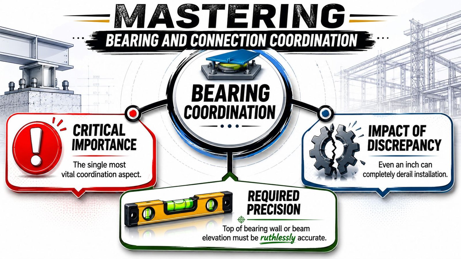
A one-inch discrepancy is enough to derail installation. If the panel sits high, the team starts asking whether shimming is acceptable. If it sits low, the wall connection and edge condition no longer perform as detailed. Either way, the job is now reacting to a coordination miss that should have been closed in model review.
Lock the bearing elevation before release
The first checkpoint is simple. Compare the top of bearing for every wall and beam against the panel support condition, not just against grid or level assumptions.
The review should answer three questions:
- Does the support elevation match across structural drawings, model views, and panel layout?
- Is any shim or seat adjustment explicitly approved by the engineer?
- Has the team checked the condition at parapets, sloped edges, and transitions, not just at typical bays?
Panelized wood roof systems also need a positive slope of at least 1/2:12 for drainage and use pre-engineered metal hangers and specific nailing patterns for assembly, as outlined in this technical overview of panelized wood roof system detailing. That means edge support and connection detailing can't be abstract. Slope, hanger type, and fastening logic all affect whether the panel can be fabricated and installed as shown.
The detail isn't finished when the section looks reasonable. It's finished when the fabricator can build it and the installer can land it without interpretation.
Model the connections people usually leave vague
The next failure point is at interior joins and perimeter diaphragm transfer.
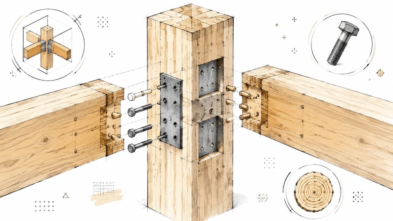
When panels meet at a ridge, over an interior beam, or along a shear wall line, the model needs the actual connection geometry. That includes the panel end condition, bearing seat, hardware, blocking if required, and the fastener logic that ties the roof diaphragm back into the wall system.
A useful review format is a short condition matrix:
| Condition | What must be shown in model | Typical failure if omitted |
|---|---|---|
| Perimeter wall bearing | Top of wall elevation, seat geometry, edge fastening | Misfit at install, gap at wall connection |
| Interior beam support | Beam elevation, panel end cut, hardware | Panel end conflict or unsupported seat |
| Ridge or panel splice | Connection type, geometry, alignment | Shop drawing revisions and field confusion |
| Shear wall tie-in | Lateral fastening and blocking logic | Diaphragm connection left unresolved |
Make sign-off explicit
This part needs discipline. The structural engineer, project architect, and fabrication-facing production lead should all sign off on bearing and connection conditions before the roof package moves.
If nobody owns that checkpoint, the shop drawings become the place where unresolved design assumptions finally collide.
Coordinating MEP Penetrations Before Fabrication
Most roof coordination failures don't come from spectacular structural mistakes. They come from ordinary penetrations that were never fully located.
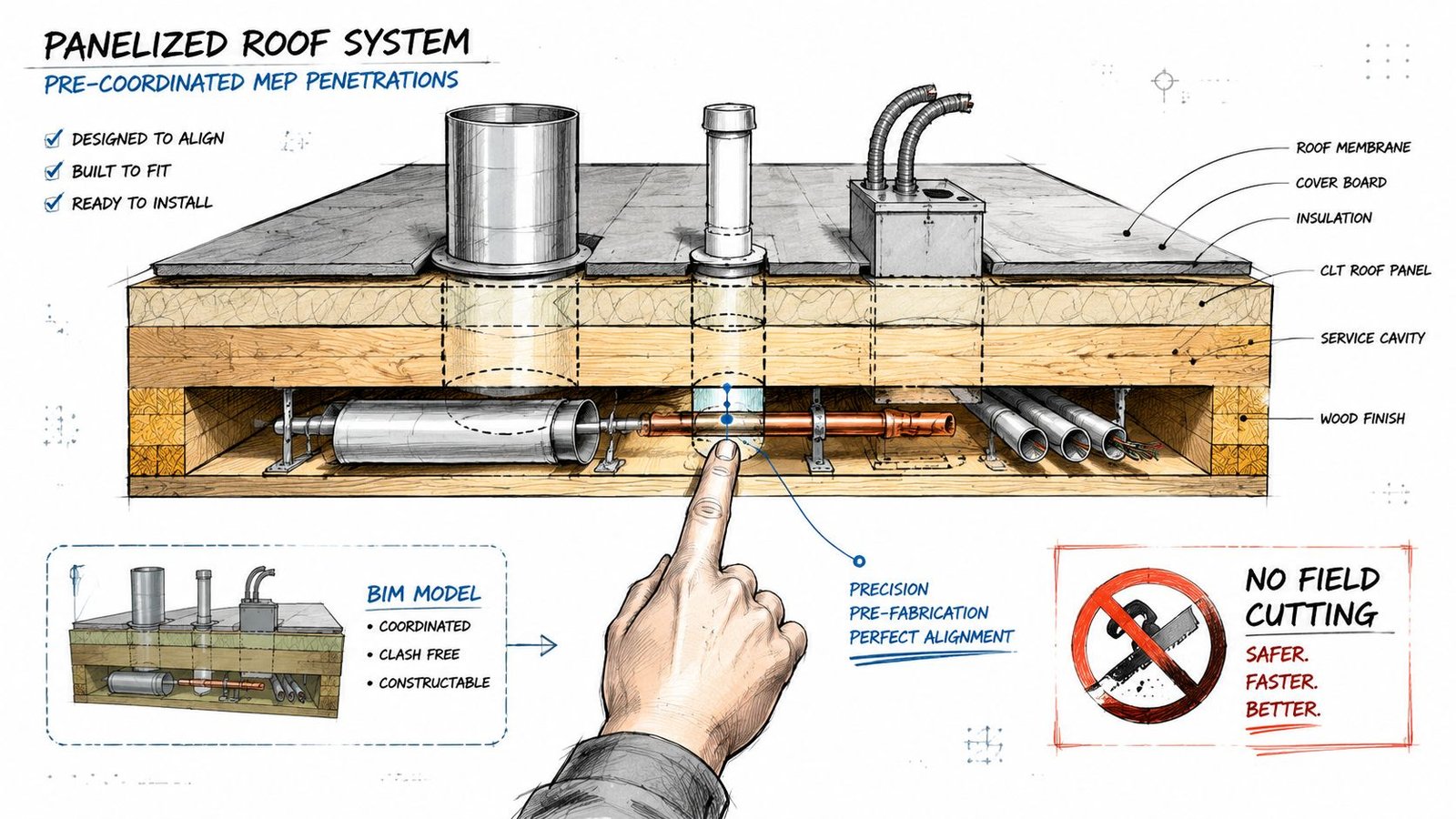
Treat the panel like a structural product, not a generic roof surface. If a curb, vent, drain, or conduit penetration gets added after fabrication, someone is now asking to cut through a finished assembly. That requires engineering review and often manufacturer approval. It also creates avoidable risk around diaphragm performance and patching.
A lot of this work gets cleaner when teams run dedicated roof opening checks instead of burying them inside broad coordination passes. That's where a focused process for clash detection in BIM coordination becomes valuable. Roof openings need their own review logic.
The openings that usually cause trouble
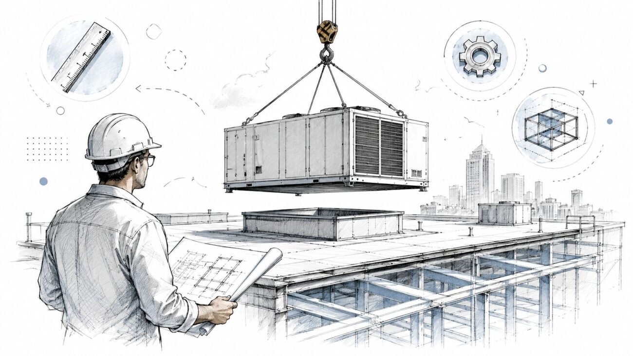
HVAC curbs are the biggest offenders because they're large, structurally significant, and often revised late. The curb opening has to be sized from the mechanical set, not from a placeholder family dropped in early design. The panel layout needs the actual opening and its location from the panel edge.
Plumbing vents are easier to overlook because they seem minor. They still need to be sized and placed before fabrication. A vent added later may require a structural patch, and nobody wants to explain that on install week.
Electrical conduit sleeves are smaller, but they belong in the same discipline. Small penetrations have a way of slipping through review because no one sees them as critical until the field asks where to drill.
Run a penetration workflow, not a markup exercise
A workable panelized roof BIM coordination sequence usually looks like this:
- Freeze equipment locations with the architectural and MEP teams before panel layout finalization.
- Confirm curb and opening dimensions from current mechanical information, not legacy schedules.
- Run a roof-specific clash review that isolates curbs, vents, drains, conduit, framing zones, and panel seams.
- Extract a penetration schedule directly from the coordination model.
- Issue the schedule with the layout package so the fabricator receives one coordinated source of truth.
If the penetration doesn't appear in the model, in the schedule, and on the layout, it isn't coordinated.
What works in production
The reliable approach is to dimension every penetration from the individual panel edge and tag it against a stable panel ID. Grid-based coordination helps designers understand the roof globally, but the shop uses panel geometry.
That's also why wood panel roof fabrication drawings need consistent family standards and annotation rules. If one pod dimensions openings from grids, another from panel extents, and a third leaves the reference ambiguous, the fabricator has to translate intent. Translation is where errors start.
The Panel Layout Plan What It Must Show
The panel layout plan is not a presentation drawing. It's the document that drives manufacturing. If the information is vague, incomplete, or dimensioned from the wrong reference, the project pays for it in redlines, reissued shops, and field confusion.
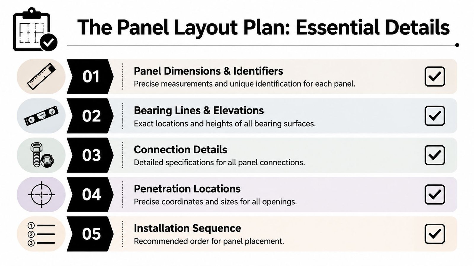
The first requirement is identity. Every panel needs a unique designation on the plan, and that same designation needs to appear on the fabricated unit for field installation. Without that tag continuity, crane sequencing and site verification become slower than they should be.
The second requirement is geometry. Width, length, slope condition, and any taper need to be explicit. Non-rectangular panels are where weak documentation usually shows itself first.
Dimension from the panel, not the building grid
This is one of the most common drafting errors in panelized roof construction documents. Designers think in grids. Fabricators build from the panel edge.
That means the layout should show:
- Panel dimensions with actual width, length, and taper
- Bearing seat locations dimensioned from panel edges
- MEP openings located from panel edges with clear size callouts
- Hardware positions tied to the panel geometry
- Panel tags that match installation marking
If an opening is only located from the building grid, the shop still has to convert it into panel-based dimensions. That extra translation step creates another chance for discrepancy.
Don't leave camber and structural depth implicit
Pre-engineered wood joists are often cambered to account for long-term dead load behavior. If camber isn't shown in the panel schedule or called out clearly on the layout, installers and reviewers start making assumptions.
There's also a deeper specification issue. For optimal structural efficiency, the lowest weight manufactured panelized roof system may use a 5.5-inch deep truss core for a specific pitch, while other climate and pitch conditions may require a 7.25-inch component, according to this paper on panelized roof system structural efficiency. That's exactly why layout plans need precise specification. Structural assumptions that stay buried in engineering logic need to appear where fabrication decisions are being made.
A panel layout plan should read like instructions for a factory, not reminders for a coordination meeting.
A practical minimum content check
Before a layout set goes out, verify this minimum package:
| Layout item | Why it matters |
|---|---|
| Unique panel designation | Enables fabrication tracking and field identification |
| Exact panel dimensions | Prevents shop interpretation and install mismatch |
| Bearing seat dimensions | Confirms support geometry at every landing point |
| Penetration locations | Locks in openings before production |
| Connection hardware and fastener pattern | Aligns shop output with structural intent |
| Camber note or schedule reference | Avoids ambiguity on expected profile |
That level of completeness is what separates usable off-site roof fabrication BIM from a drawing set that still expects the field to improvise.
The Fabricator Coordination Workflow
The panel fabricator shouldn't be treated like the last stop in the chain. On a strong project, the fabricator acts like a design-assist partner with manufacturing knowledge the design team needs before release.
That starts with an intentional review cycle. Send the coordinated model or preliminary layout for review before final panel release, not after. The fabricator can then compare the proposed geometry against actual fabrication constraints, staging realities, and transport limitations.
This is also where teams benefit from studying how disciplined shop drawing workflows reduce revision churn. The same principle applies here. Better upstream structure produces cleaner downstream documents.
What the fabricator should review early
Every fabricator has limits tied to equipment and shipping. Panel width may need to stay within a shop's production setup. Long roof sections may be constrained by transport route or permitting.
The review needs to answer practical questions such as:
- Can the proposed panel widths be manufactured as drawn?
- Does the panel length create transport issues that require redesign or splitting?
- Do standard connection details support the intended geometry?
- Are material and assembly assumptions aligned with project performance requirements?
Hybrid panelized systems are increasingly common, and high-performance panels can achieve an FM-rated wind uplift rating of 135 mph, as noted in this WoodWorks presentation on large panelized roof systems. That makes early coordination on material specs and assembly conditions more than a convenience. It's how teams keep performance requirements aligned with buildable shop output.
Put the review cycle in the schedule
Fabricator review usually takes one to two weeks. If the project schedule doesn't carry that duration as a real checkpoint, the team will compress it until review becomes ceremonial.
That's when problems get pushed into shop drawings, and shop drawings come back full of corrections that should have been solved earlier.
A disciplined sequence is simple:
- internal QA on the model and layout
- design team coordination review
- fabricator review and redlines
- updates and final sign-off
- release for fabrication
The workflow matters because panelized roof systems reward teams that make decisions once.
Common Errors That Derail Panelized Roof Projects
The same failures show up over and over, and they're rarely mysterious. They come from incomplete modeling, loose handoffs, or missing decision checkpoints.
The first is inconsistent bearing elevation between structural drawings and panel documents. Teams often assume a typical support condition and fail to reconcile actual wall height, beam elevation, and seat geometry before release. The result is immediate field friction.
The second is incomplete connection information. A ridge join, interior splice, or perimeter diaphragm tie gets referenced generally but never fully modeled. Then the shop has to guess, or the field has to wait.
The errors worth catching in QA
A good production QA pass should actively look for these issues:
- Bearing mismatch between the structural model, details, and panel layout
- Missing panel-to-panel details at ridges, beams, and split conditions
- Uncoordinated HVAC curb openings that never made it into the layout
- No penetration schedule issued from the coordination model
- Panel widths beyond fabricator capability or transport practicality
- Camber omitted from notes or panel schedule
- Panel tags missing from the layout plan used in the field
Why these mistakes keep happening
Most of them come from teams using conventional documentation habits on a fabrication-led scope. The roof package gets advanced with partial information because the model looks complete enough for design intent, even though it isn't complete enough for manufacturing.
That distinction matters.
A model can look clean in 3D and still fail as a fabrication instrument if the references, annotations, and schedules don't line up. That's why panelized roof construction documents need tighter template discipline than standard permit output. Shared parameters, naming conventions, sheet standards, and QA checklists aren't administrative extras here. They are margin protection tools.
The project doesn't lose money because panelized roofs are risky. It loses money because unresolved decisions were released as if they were finished.
From Model Certainty to Site Predictability
Panelized roof systems don't forgive loose coordination, but they reward disciplined teams. When the model becomes the single source of truth for bearing, connections, penetrations, and panel identity, the site gets a roof package it can install instead of reinterpret.
This provides key advantages. Fewer RFIs. Less field redesign. Cleaner permitting prep. More reliable fabrication review. Better operational consistency across teams and projects.
For project architects, structural engineers, and BIM coordinators, this is less about software than decision control. Strong templates, repeatable QA, and hard release checkpoints are what keep off-site delivery profitable. The firms that do this well aren't drawing faster. They're reducing ambiguity before it becomes cost.
If your team wants a stronger workflow for panelized roof BIM coordination, BIM Heroes can support the production side with architectural services, model QA, fabrication-facing documentation, and repeatable delivery systems. If it would help, reach out through their architectural production services page for practical support, templates, or a clearer review framework on your next panelized roof project.
Suggested WordPress category: BIM Technology & Workflows