Meta description: Learn how to read and produce a residential framing plan that works in the field, including floor framing plan and roof framing plan basics, framing plan symbols, coordination checks, and pre-framing verification.
A framing crew can lose an hour fast on a sheet that looked fine in the office. One framer reads the joist arrows one way, the lead thinks the beam pocket lands over a different wall line, and someone calls the GC because the header on plan doesn't match the opening on elevation. The problem usually isn't that nobody knows how to build. The problem is that the drawing set forces the field to interpret instead of execute.
That same gap shows up in permit review. A GC flips between architectural sheets, structural notes, and a header schedule trying to confirm whether the residential framing plan reflects the engineer's intent or just gestures at it. If the framing sheet leaves too much unsaid, the questions don't stop at plan check. They show up in layout, in RFIs, in rework, and in inspection.
Good residential framing plans remove ambiguity before lumber hits the deck. They tell the crew what spans where, what bears where, what changes from typical conditions, and which details matter enough to stop and verify. They also need to line up with the larger production system: permit drawings, structural backing, truss packages, and how the site team builds.
What a Framing Plan Actually Documents
A residential framing plan is the structural map the builder follows to assemble the skeleton of the house. It shows the layout of joists, rafters, trusses, beams, headers, and bearing points. More important, it shows how those pieces relate to each other so loads can travel down through the structure in a controlled way.
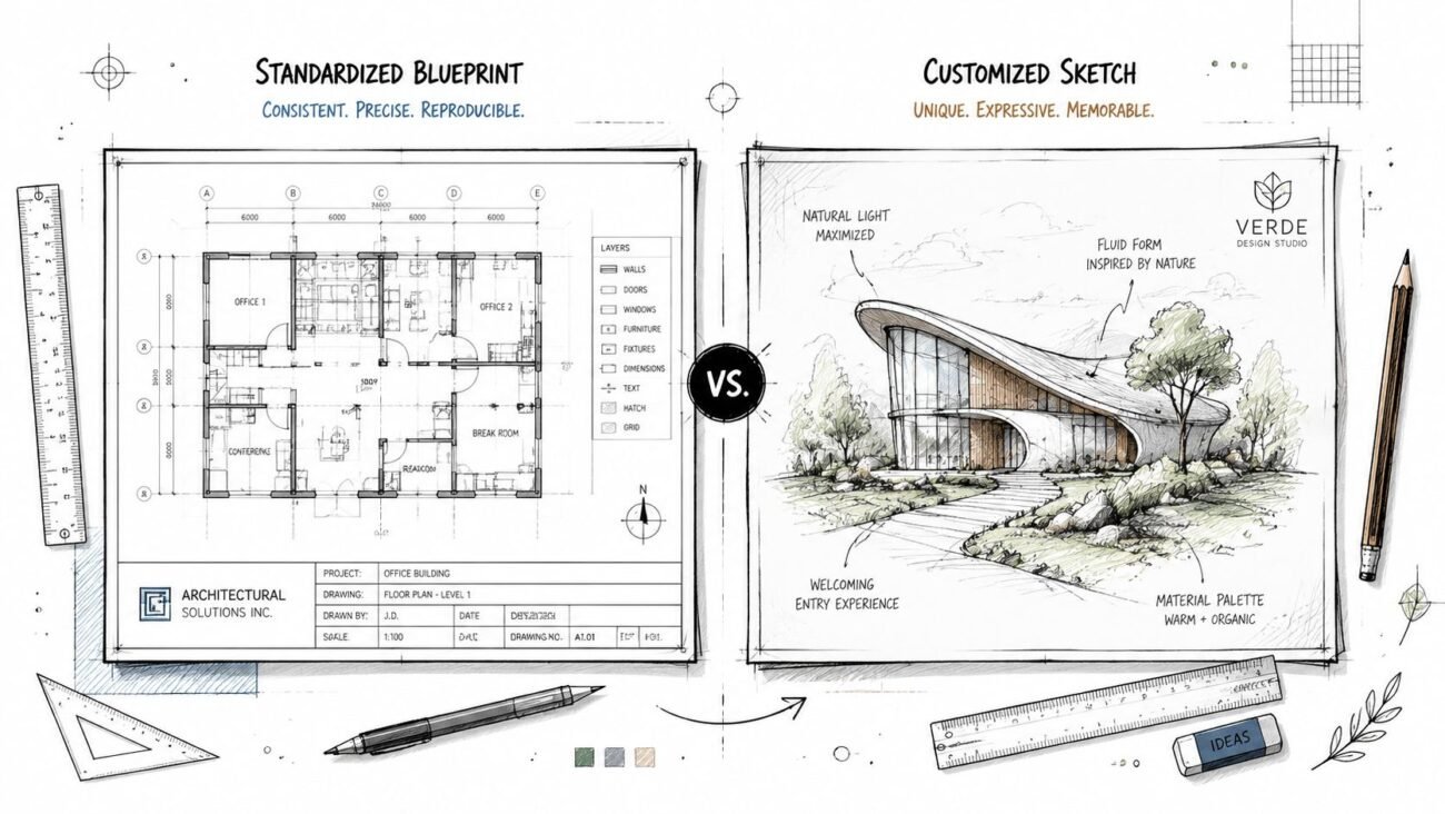
That makes it different from an architectural floor plan. The floor plan tells you where rooms, doors, and walls belong for use and layout. The framing plan tells you which members carry weight, what direction they span, how they're spaced, and where support is required. If someone treats those sheets as interchangeable, field errors follow.
In the U.S., that matters on almost every house. Wood framing accounted for 94% of completed single-family homes in 2024, with about 959,000 wood-framed homes completed, which is why clear framing documentation remains central to residential production according to NAHB analysis of U.S. Census Bureau data.
What the sheet is really answering
A working framing plan answers a short list of site questions:
- What spans where: joist and rafter direction, beam lines, truss runs
- What supports what: bearing walls, point loads, posts, pockets
- What changes from typical: doubled members, dropped beams, special headers
- What the crew can trust: dimensions, references, schedules, and keyed notes
The field doesn't need a beautiful sheet. It needs a buildable one.
Practical rule: If a framer has to hunt through five sheets to confirm one bearing condition, the plan set isn't coordinated enough.
For junior production staff, it helps to study how framing sheets sit inside the broader set of building construction drawings. The framing plan isn't a duplicate of architecture. It's the translation from design intent into structural layout.
The Difference Between Floor and Roof Framing Plans
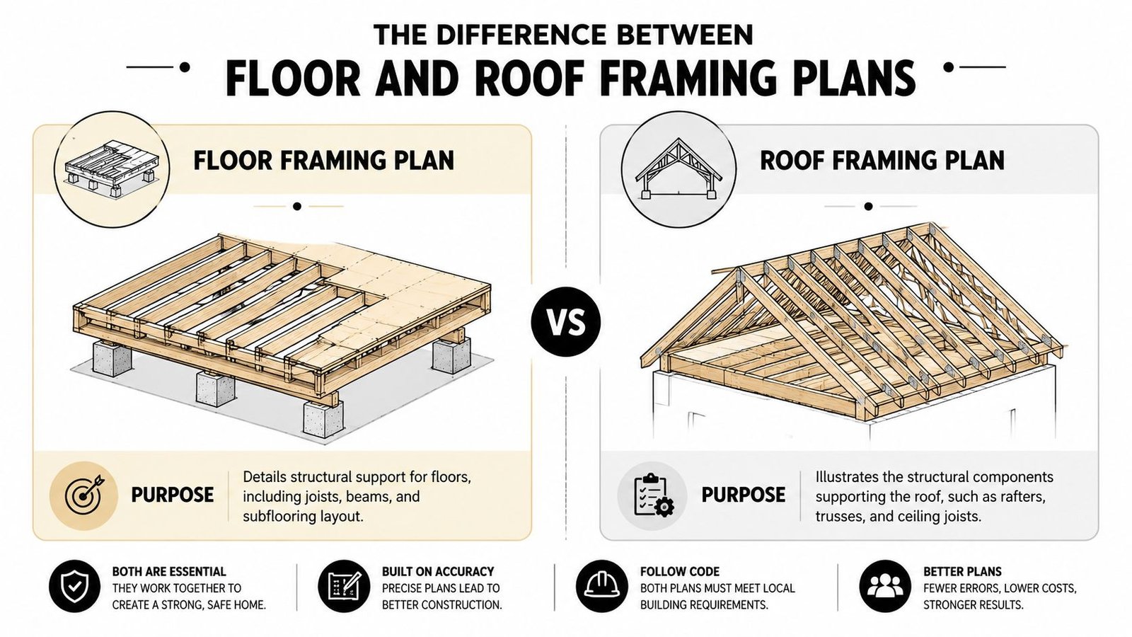
A floor framing plan and a roof framing plan solve different problems. They're related, but they shouldn't be read the same way.
Floor framing plan
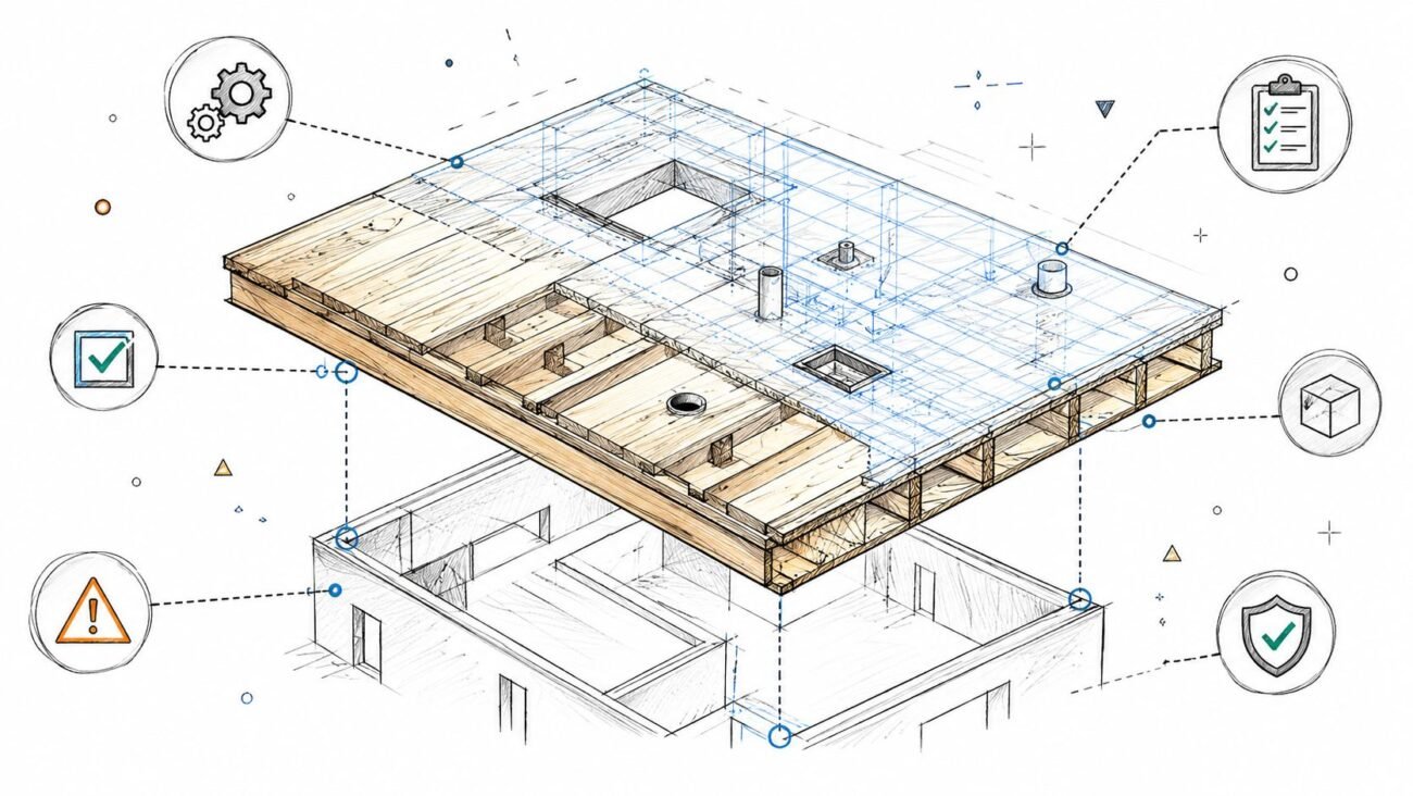
A floor framing plan shows how the occupied levels are supported. The key information is usually joist direction and spacing, beam and girder locations, bearing lines, point loads coming down from above, and floor sheathing notes. On a real project, this sheet is where crews confirm whether the framing system matches the room arrangement or fights it.
When a floor plan has large openings, offset walls, stair cuts, or concentrated loads, the floor framing plan has to make that obvious. Hidden assumptions don't survive contact with the field. If a point load from above lands between members below, someone will either stop for clarification or build a fix in place. Neither outcome helps schedule.
Roof framing plan
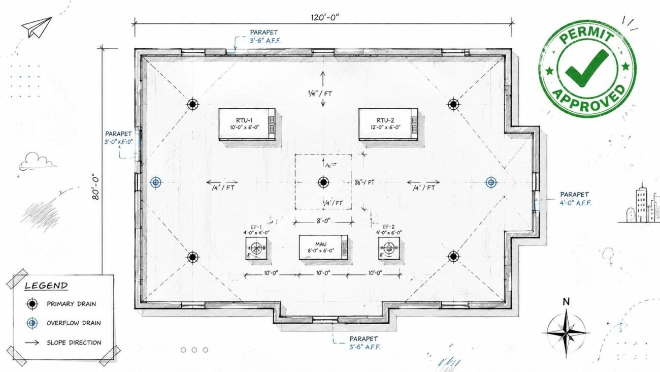
A roof framing plan deals with an entirely different set of decisions. It shows rafter or truss layout, ridge beam location, hips, valleys, roof sheathing, and support conditions tied to the geometry of the roof. This sheet is less about room layout and more about making sure the roof shape can be framed as drawn.
The biggest coordination failure usually appears when the architectural roof framing intent and the truss package drift apart. The plan may show one framing logic while the manufacturer's shop drawings use another. If that mismatch isn't caught early, overhangs, bearing locations, ridge heights, and web locations start colliding with what the field expected.
Don't assume a roof framing plan is complete just because the roof shape is clear. Roof geometry and roof support are not the same thing.
The fast read in the field
When checking either sheet, look for the governing question first.
- On floor sheets: Where do loads go, and what supports them below?
- On roof sheets: How is the roof shape framed, and does it match the approved truss or rafter approach?
That simple distinction makes how to read a framing plan much faster on site.
How to Read Framing Plan Symbols and Callouts
Most framing confusion starts in shorthand. The sheet may technically include the answer, but the answer is buried in abbreviations, bubbles, arrows, and schedule tags that only make sense if you know what each one is doing.
Start with the member callout
The first thing to read is the member notation itself. That usually tells you size, material description, spacing, and sometimes grade or species. The point isn't to memorize every office standard. The point is to read the note as an instruction tied to a specific condition.
If the callout says studs at a certain spacing, verify that the wall type and story condition allow it. For example, in conventional wood framing references, one-story exterior walls are typically framed at 16 inches on center, while 24-inch spacing of 2×4 studs can be acceptable when sheathing or siding thickness can bridge the gap. In three-story buildings, bottom-story studs must be at least nominal 3×4 or 2×6 and can't exceed 16-inch spacing per the American Wood Council details cited here.
Read arrows, tags, and references together
Direction arrows matter because they tell the field which way joists or rafters span. A joist arrow isn't decoration. It tells you where bearing should occur and where the load path starts. If the arrow conflicts with wall layout or beam placement, stop there and resolve it before layout.
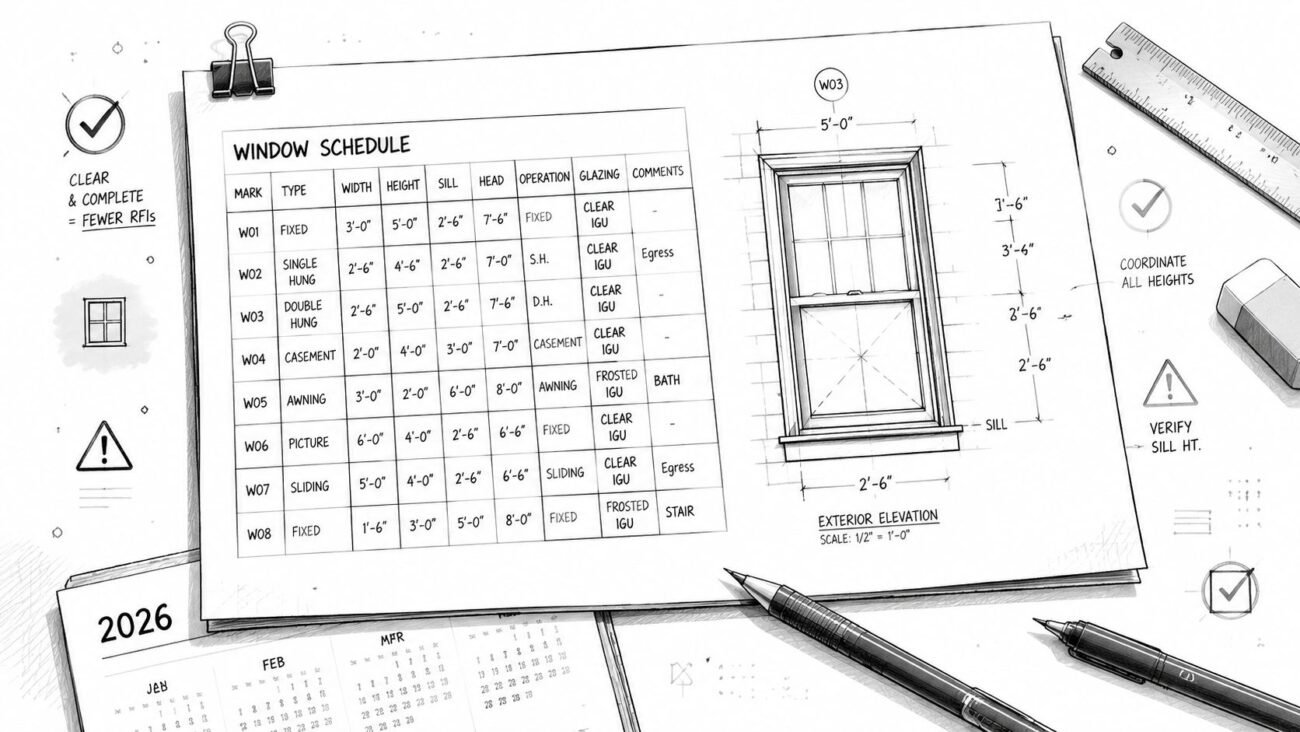
Connection callouts matter just as much. Hanger notes, ledger notes, and hardware references often sit in small text near intersections where mistakes are expensive. Header tags also deserve attention. Many plans use a symbol on plan and push the actual size to a schedule elsewhere in the set. That works only if the plan, opening width, and schedule all agree.
| Symbol | Meaning | Example Callout |
|---|---|---|
| Arrow | Span direction | Joists span this direction |
| B or Beam Tag | Beam reference | B1, see structural schedule |
| H or Header Tag | Header reference | H3 at window opening |
| BW | Bearing wall | Provide support below |
| Hanger note | Connection hardware required | Install hanger per detail |
Small symbols cause large mistakes. Treat every tag as a pointer to another decision, not as a complete instruction by itself.
What usually gets missed
Three things get skipped more than they should:
- Bearing indicators: A beam line without confirmed support below is only half-documented.
- Beam pockets: These need to be buildable in the wall thickness shown.
- Header schedules: The opening on elevation, the rough opening on plan, and the header table must agree.
At this stage, framing plan symbols stop being drafting language and start affecting production.
Framing Plan vs Structural Plan
The question comes up on nearly every residential job: is the framing plan the structural plan, or is it just a layout sheet? In practice, the cleanest answer is this. The framing plan shows the arrangement of the members. The structural basis behind it comes from either prescriptive code provisions or engineered design.
Prescriptive work and engineered work
On straightforward residential projects, conventional construction may use prescriptive code tables for spans and framing rules. In those cases, the drawing still needs to be explicit. The fact that a member came from a code table doesn't excuse vague documentation.
Once the project moves into higher wind, seismic, unusual loading, complex geometry, or non-typical conditions, engineering usually becomes the controlling path. That's where a lot of confusion starts, because people still assume a “typical house” doesn't need much framing documentation.
A common industry assumption is that “framing plans are typically not included because they are not needed” for typical houses, but that misses the fact that wind and seismic design by a licensed engineer often requires them in higher-risk zones, especially where code compliance demands engineered framing plans, as discussed in this industry conversation on house plan documentation.
Why the distinction matters in production
Problems start when a set mixes prescriptive assumptions with engineered conditions and doesn't label the boundary clearly. The field doesn't know what can be treated as typical and what must follow a stamped detail exactly. Plan reviewers don't like it either.
That's why the framing plan vs structural plan question is really a documentation question. The framing sheet has to reflect the actual basis of design. If the project team is moving between CAD output, consultant input, and coordinated production models, the handoff needs to stay clean. Teams that build this well usually have stronger BIM modelling services behind the scenes, because model coordination exposes mismatches before permit and before site work.
A framing plan is trustworthy only when it matches the design path that sized it.
Common Coordination Gaps That Cost Time and Money
The expensive mistakes rarely come from one dramatic error. They come from ordinary gaps between trades and sheets.
The joist bay that already belonged to someone else
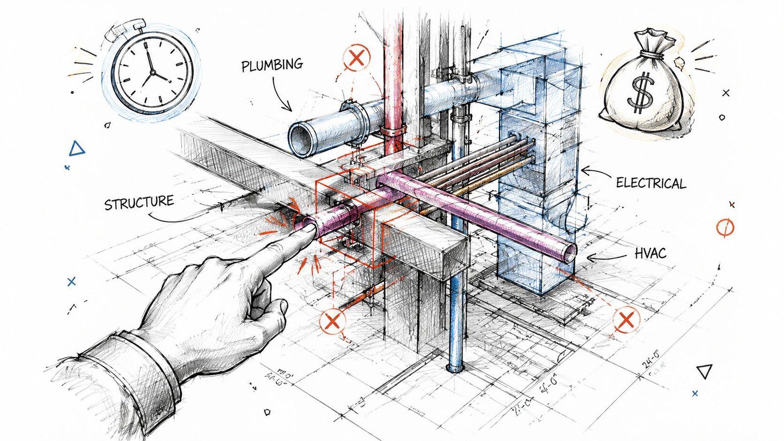
A floor framing plan may look clean until plumbing wants the same space for a drain run, or mechanical wants a chase where the joists are densest. If those routes weren't considered early, the field starts asking whether members can be cut, drilled, or shifted. That question tends to arrive after framing is underway, when every answer costs more.
Electrical can create a quieter version of the same problem. Panel feeds, lighting drops, and recessed conditions don't always need major framing changes, but they do need predictable space. If the plan set treats those needs as someone else's problem, the site team ends up improvising.
The roof package that doesn't match the roof intent
Another common miss happens at the roof. The architectural set shows a clean roof framing concept. The truss supplier sends shop drawings that solve the roof differently. Maybe the bearings move. Maybe web locations interfere with attic access or equipment. Maybe a girder truss changes how loads stack below. If nobody reconciles the two sets, the crew catches it in the middle of production.
This is the kind of issue people mean when they talk about unseen pitfalls in property development. The visible drawing isn't always the actual risk. The risk is what wasn't coordinated behind it.
Loads that never made it onto the sheet
Heavy equipment, tubs, concentrated point loads, and specialty framing zones often get discussed in meetings but never fully land on the framing plan. The result is a sheet that looks complete until the installer asks where support is supposed to come from.
A reliable production workflow catches these before issue:
- MEP penetrations: review structural restrictions before routing is accepted
- Equipment loads: place support requirements on the framing sheet, not just in notes
- Truss coordination: reconcile truss shop drawings against the approved roof framing intent
- Wall framing below: confirm every major load has a real bearing path
A Builder's Pre-Framing Verification Checklist
A solid pre-framing review is less about paperwork and more about removing guesswork before the first crew starts layout.
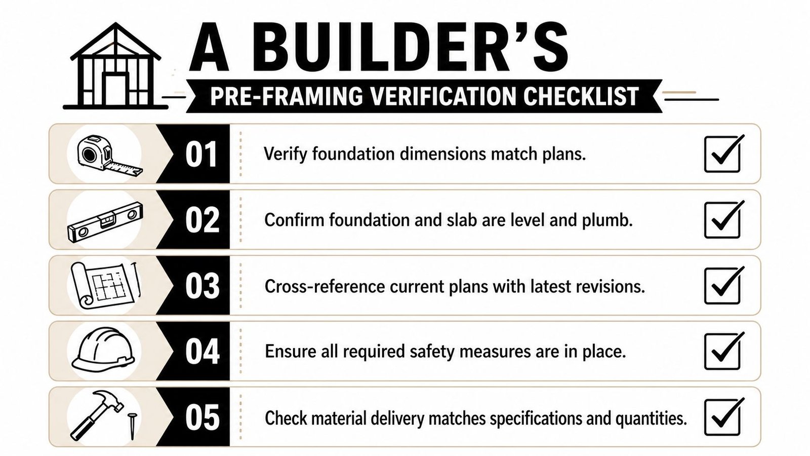
Start by comparing joist direction to the room arrangement and the actual support lines below. If the plan says the joists run one way but the bearing walls and beam pockets suggest another, don't assume it will sort itself out on site. Resolve it before material gets cut.
Then check that beam pockets, posts, and bearing points are physically buildable within the wall framing shown. A beam may work structurally on paper and still fail in the field if the pocket depth, wall thickness, or stacked supports don't line up. Header sizes deserve the same treatment. Read the header schedule, then compare it against actual opening widths on plans and elevations rather than trusting that the tags were coordinated.
Roof verification that saves headaches
Roof review needs its own pass. Confirm that the truss or rafter layout matches the roof geometry, especially at overhangs, ridge conditions, hips, and valleys. If shop drawings are in play, compare them directly against the roof framing plan before the framing crew starts.
One field item shouldn't be left to inspection day. Failure to install required firestop blocking or bridging for joist spans exceeding 8 feet shows up in about 30% of inspected residential framing projects, according to InterNACHI's framing inspection guidance here. That kind of miss isn't minor. It affects both structural stability and fire safety compliance.
Check what the inspector will check, but do it before the inspector arrives.
The short version
Before framing starts, verify these conditions in the current issued set:
- Joist direction: does it agree with support below and room geometry?
- Bearing locations: can the walls and pockets shown receive the load?
- Roof layout: does the field package match the approved roof geometry?
- Headers: do schedule sizes match actual opening conditions?
- Blocking and bridging: are required locations called out clearly enough to be installed without reminder?
Producing Framing Plans That Prevent Field RFIs
The best framing plans aren't the prettiest sheets in the set. They're the ones the field can build from without a phone call.
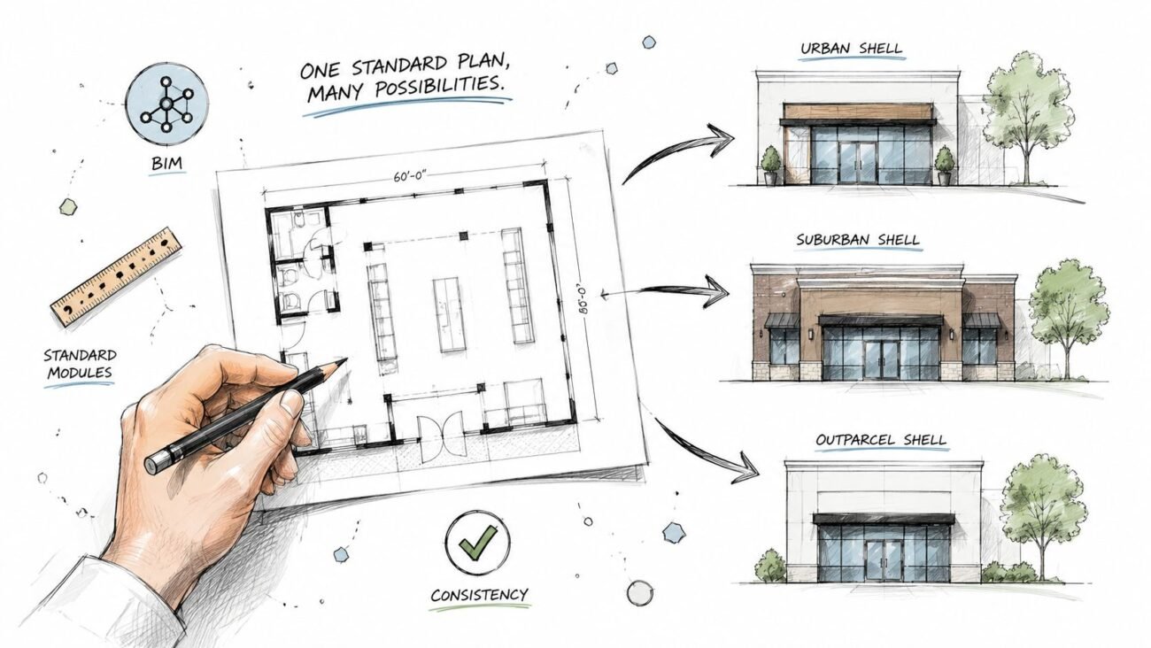
That takes production discipline. The framing plan has to match the actual system selected for the job, whether that means conventional stick framing, engineered members, or a truss-driven roof package. It also has to coordinate with sections, elevations, door schedules, and consultant input so the crew isn't forced to assemble the answer from fragments.
That matters because framers often have to infer critical details by cross-referencing floor plans, sections, ceiling information, and schedules, and that interpretation gap drives rework. The cost impact isn't abstract when framing costs average $7 to $16 per square foot, or about $15,000 to $30,000 for a 2,000 square foot home, as noted in this field-focused video discussion of framing plan interpretation.
Production maturity shows up in repeatable habits:
- Template discipline: standard notes, schedules, tags, and detail references stay consistent
- Decision checkpoints: roof package, loads, and bearing paths are verified before issue
- QA review: someone reads the sheet like a superintendent, not just like a drafter
- Model-to-sheet control: if the job is moving through BIM, the sheets reflect the model that was coordinated
For teams tightening documentation standards, good shop drawings for construction are part of the same discipline. The point isn't more drawing. It's fewer assumptions.
If your team needs sharper residential framing documentation, clearer permit sets, or production workflows that reduce RFIs before they reach the site, BIM Heroes offers architectural production services built around coordination, template discipline, and field-ready output. If helpful, start with a checklist, a review framework, or a second set of eyes on a live drawing package.