A hospital renovation reaches final medical gas inspection and fails on paperwork, not pipework. The inspector sees that the zone valve boxes aren't where the drawings say they are, the outlet testing data isn't carried into the set, and the alarm panel locations were never documented. The contractor may have installed the system correctly, but in a medical gas system, correct installation isn't enough if the documents don't match what was built.
That's where teams lose time, burn fee, and invite RFIs they should've prevented in production. On healthcare work, the drawing set has to function as a safety document, not a loose design intent package. What matters is whether the plans, details, schedules, and notes give the installer, verifier, and inspector one unambiguous story. If they don't, the job stalls.
Introduction
Most inspection failures on medical gas work don't start with a catastrophic field mistake. They start with a drawing gap that looked small during production. A valve box wasn't tagged to a zone. An alarm panel was coordinated in conversation but never placed on the electrical plan. Outlet data existed in a test form, but not where the inspector expected to verify it against the set.
That's the trap. In a medical gas system, the installation has to match the documents precisely enough to support inspection and verification. If the set is incomplete, the field team inherits ambiguity they can't safely improvise around.
This article focuses on what NFPA 99 medical gas drawings need to show, how that information should be organized in a healthcare drawing set, and which documentation gaps most often trigger failed inspections, RFIs, and expensive redraw cycles.
The NFPA 99 Mandate for Medical Gas Systems
NFPA 99 is the core US standard governing healthcare facility systems where failure can affect patient care. Before a medical gas system can be placed into service, it must meet NFPA 99 standards, and the code classifies systems into four risk levels: Category 1 could cause major injury or death, Category 2 could cause minor injury, Category 3 is unlikely to cause injury but could disrupt care, and Category 4 has no impact on patient care, as summarized in the NFPA 99 risk category guidance.
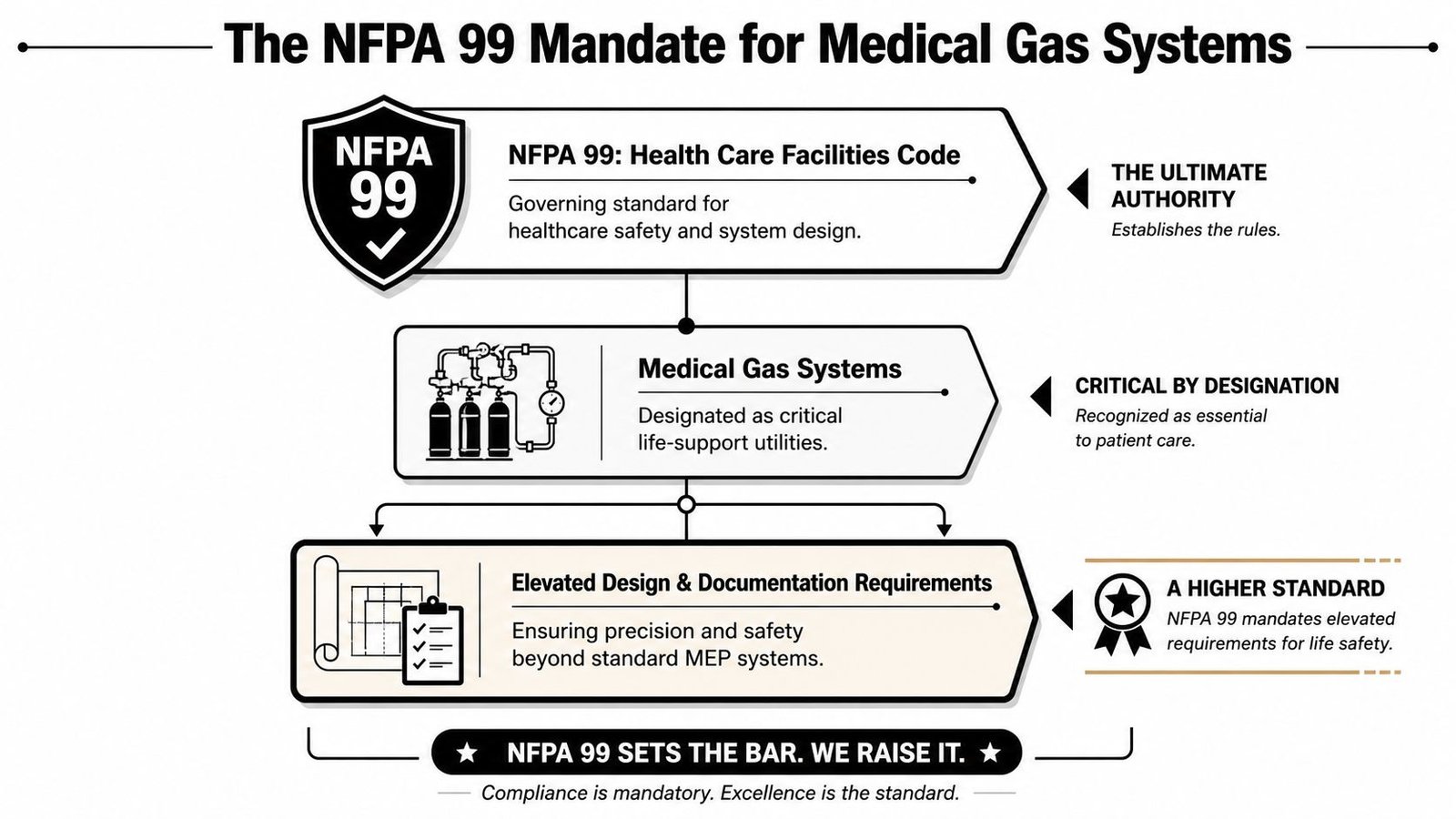
Why these drawings are held to a higher standard
Chapter 5 is where the pressure rises for the design team. It governs piped medical gas and vacuum systems, and it assumes the documents are being produced by a qualified designer, typically a licensed engineer. The practical implication is simple. The set can't rely on installer interpretation the way some standard MEP sheets still do.
If a domestic water branch is vague, the field team may solve it with a coordination sketch. If a medical oxygen branch is vague, that same habit can create a patient safety problem, a failed verification, or both.
Practical rule: If an inspector or verifier has to guess what a symbol, zone, or terminal serves, the set isn't ready.
Separate systems, separate documentation
A generic combined plan is one of the fastest ways to undermine a hospital medical gas permit submission. Each system needs to be documented distinctly because the source equipment, distribution requirements, and terminal devices aren't interchangeable.
That includes:
- Medical oxygen
- Medical air
- Nitrous oxide
- Carbon dioxide
- Nitrogen
- Medical vacuum
- Waste anesthetic gas disposal
The mistake isn't just graphic. It's procedural. When teams collapse these systems into one undifferentiated overlay, they usually also collapse notes, schedules, and testing references. That's when outlet designations drift away from specs, alarm monitoring gets under-documented, and the permit comments start.
For teams that also coordinate broader utility systems, it helps to stay grounded in reliable commercial plumbing information so medical gas documentation doesn't get treated like a standard plumbing add-on. It isn't.
Documenting Source Equipment and Central Supply
The drawing set has to prove that the system is sound at the source before anyone looks at a patient room plan. Source equipment is where permit reviewers and inspectors often test whether the team has done real coordination or just placed manufacturer blocks on a sheet.
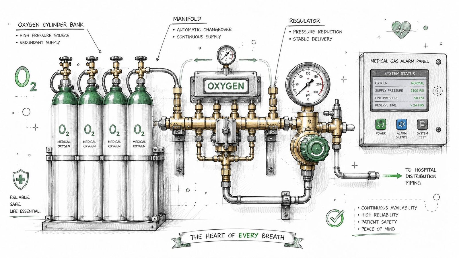
Oxygen source documentation
For oxygen, the set needs to identify whether the project uses bulk liquid oxygen storage or a manifold cylinder system. Show the equipment footprint, connection to distribution piping, and the required setbacks from building openings and ignition sources. If those setbacks are left to a deferred submittal or informal site coordination, expect comments.
Storage rules matter here. Healthcare facility guidance on recent CMS-related medical gas regulations states that locations storing oxidizing gases greater than 300 but less than 3,000 cubic feet must be in an outdoor enclosure or an enclosed interior space of noncombustible construction with secured doors, and oxidizing gases must be separated from combustible materials by at least 20 feet, or 5 feet if protected by an automatic sprinkler system.
Medical air and vacuum rooms
Medical air rooms need more than a room tag and a keynote. Show the compressor layout, intake location, exhaust path, and monitoring requirements. If the medical air system serves patient care areas, document it accordingly as a critical system within the overall code framework. On renovations, the biggest failure point is poor architectural coordination around louvers, windows, doors, and adjacent intakes.
Medical vacuum pump rooms need the same discipline. Document the pump layout, connection to vacuum mains, and exhaust discharge away from air intakes. If that exhaust path is vague, field routing changes start late and cost real money.
Good source equipment sheets answer installer questions before the first RFI is drafted.
Manifolds and production coordination
Smaller facilities and fit-outs often use cylinder manifolds. In those cases, the manifold room location, cylinder storage area, and automatic changeover arrangement all need to be shown, not implied. Consequently, production teams should build repeatable detail packages and room templates instead of redrawing from scratch each time.
A mature healthcare workflow usually includes a source equipment decision checkpoint with architecture, plumbing, and electrical before permit issue. That checkpoint catches room access conflicts, alarm power coordination, and site spacing problems while the model is still easy to fix.
Teams working through central utility documentation often benefit from studying adjacent field problems, including solving gas line delays at VA, because many delays come from incomplete routing and approval logic, not from fabrication. For related healthcare utility production standards, it also helps to align the sheet package with strong plumbing design workflows.
Planning and Sizing Distribution Piping
Distribution piping is where an incomplete model becomes an expensive construction issue. In a medical gas system construction documents package, every segment needs to tell the field team what it is, what size it is, and what zone it belongs to. If any one of those is missing, the set becomes interpretive.
What the piping plan must make explicit
Pipe sizing isn't optional notation. The qualified designer performs the sizing calculations, and the sizes shown on the plans have to reflect that engineering work. Don't leave branch sizes floating to risers, details, or schedules that don't fully reconcile.
Material identification also needs to be direct. Medical gas pipeline systems must use unwelded copper pipes with fluxless silver brazing compliant with ASTM standards, and they're intercepted by Area Valve Service Units (AVSUs) every clinical sector to isolate gas delivery during maintenance or emergencies, according to the medical gas pipeline system requirements published in PMC.
That means the plans should do three things clearly:
- Label each pipe segment with system and size.
- Call out the pipe material and cleaning requirements in notes and details.
- Show every AVSU with the controlled downstream area identified.
Zone valve boxes are not annotation filler
A surprising number of failed reviews come down to valve boxes that exist in concept but not in document logic. The plan needs to show where each zone valve box sits, what area it isolates, and how someone in the field can identify it without interpretation.
That's why I push teams to stop treating zone valve boxes as symbols dropped late in documentation. They need to be part of the model structure from the beginning. If the architecture changes room boundaries and the gas zones don't update, the sheet may still look complete while the control logic is already wrong.
A disciplined medical gas piping BIM workflow should also include view templates that visibly distinguish each gas service and associated valve box tags. That's the only practical way to keep renovations, tenant improvements, and floor-by-floor hospital work from drifting.
For firms still tightening production standards, clean isometric drawings for plumbing can help expose where plan views hide riser complexity, branch transitions, and shutoff sequencing.
Pressure and flow belong in the package
The drawing set also needs to communicate design pressure and flow for each zone, either directly on the sheets or through clearly referenced calculations. On healthcare work, hidden engineering is usually treated as missing engineering.
If a contractor can build it but a verifier can't confirm it from the set, the documents are incomplete.
Detailing Terminals, Alarms, and Monitoring
The point of use is where documentation errors become highly visible. Nurses, facilities staff, inspectors, and verifiers all interact with terminal devices and alarm locations in ways they don't with concealed mains. That's why these sheets need a different level of precision.
Outlets and inlets must be verifiable
Every outlet and inlet should be identified by gas type, configuration, and designation that matches the manufacturer language used in the specification. If your plans use one naming logic, the schedules use another, and the spec uses a third, the contractor has to reconcile your package for you.
Location matters just as much as naming. The plan should dimension outlets clearly enough that someone can verify placement relative to the patient bed, headwall, procedure area, or equipment served. Don't rely on graphic proximity alone in dense rooms.
A reliable terminal documentation set usually includes:
- Room-by-room outlet counts that can be checked against room type requirements.
- Symbol differentiation between gas services and vacuum inlets.
- Label references that align with the specified manufacturer catalog designation.
- Mounting and rough-in details coordinated with architectural assemblies.
Alarm panels and monitored zones
Master alarm panels need to be shown in the principal working areas associated with the medical gas system. In practice, that often means locations tied to engineering operations and nursing oversight. Area alarm panels need to be placed outside each zone served, and the monitored zone has to be identified.
Sheet ownership often breaks down. Mechanical may assume electrical will carry the panel. Electrical may assume it lives on the med gas sheet. The permit reviewer only sees that no one documented it completely.
A better production rule is simple. Put the panel where it belongs in every affected discipline, then cross-reference it. Don't make the reviewer stitch together intent.
WAGD is where sloppy labeling gets punished
Waste anesthetic gas disposal systems deserve special attention in renovations, surgical projects, and any work involving dual-use piping conditions. CSE Magazine's discussion of the evolution of medical gas systems design notes that NFPA 99 2021 mandates explicit valve labeling for WAGD systems to prevent cross-connections with surgical vacuum, yet 30% of system failures stem from alarm malfunctions or unmarked outlets.
That should change how you detail these systems. WAGD labeling, valve identification, alarm connections, and detail references should never be left to generic vacuum notes.
The field rarely gets confused by the detail you included. It gets confused by the detail you assumed was obvious.
Testing responsibility also needs to be noted. The drawing set should identify that complete system testing is required before occupancy and make responsibility traceable through notes, specs, and submittal expectations.
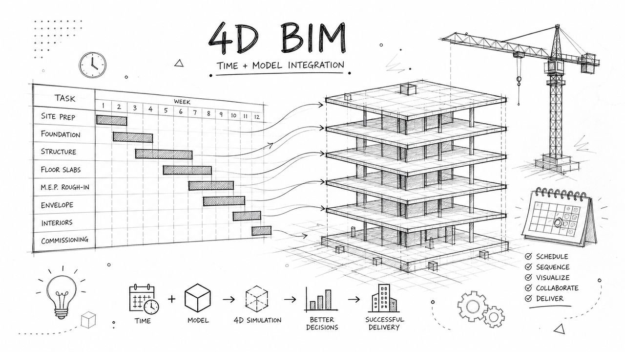
Medical Gas Systems in a BIM-First Workflow
Knowing the code doesn't guarantee a clean deliverable. Teams get into trouble when the code sits in the engineer's head but never gets translated into model standards, family behavior, and sheet QA. A BIM-first workflow closes that gap.
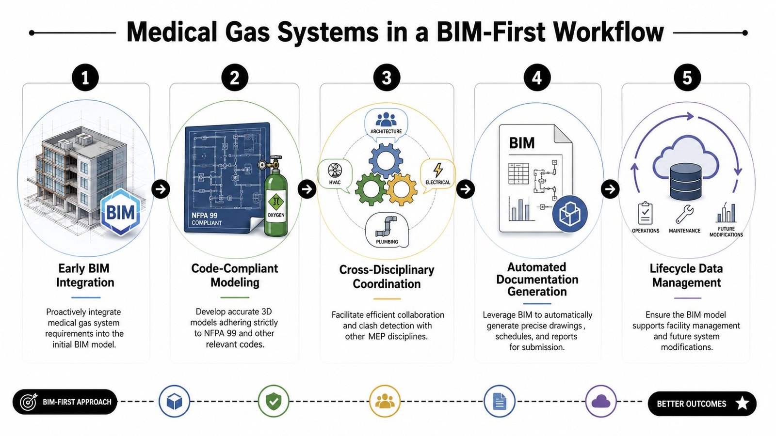
Start with the execution plan, not the model
The best healthcare teams define medical gas requirements in the BIM Execution Plan before anyone starts routing. That means naming conventions, system abbreviations, family parameters, view templates, sheet ownership, and level of development expectations are set early.
If you skip that step, every downstream task gets slower. Families get built inconsistently. Schedules don't sort cleanly. Zone tags don't reconcile. Clash reviews become visual exercises instead of decision sessions.
A practical setup usually includes a model standard for:
| Component | What the family or object should carry |
|---|---|
| Source equipment | System type, service, room, connection points |
| AVSUs | Zone served, valve ID, accessibility note |
| Outlets and inlets | Gas service, configuration, manufacturer designation |
| Alarm panels | Panel type, monitored zone, sheet cross-reference |
| Piping | Service name, size, material note, riser reference |
Build families that support documentation
A medical gas model fails when families look good in 3D but don't drive drawings. Families need parameters that support schedules, tags, filters, and detail references. If a zone valve family can't report the zone served, it's not finished. If an outlet family can't distinguish service and configuration, it's decoration.
Template discipline protects margin. Instead of solving the same metadata problem project by project, production teams should keep a vetted healthcare content library with approved symbols, naming logic, annotation tags, and coordinated sheet standards.
That's also where CAD-to-BIM evolution matters. Legacy 2D standards often hide assumptions in keynote legends and general notes. BIM exposes those gaps fast. If the family, tag, and schedule can't agree, the old standard wasn't adequate.
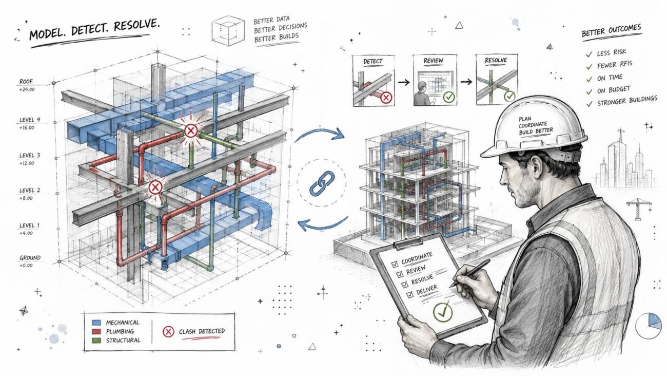
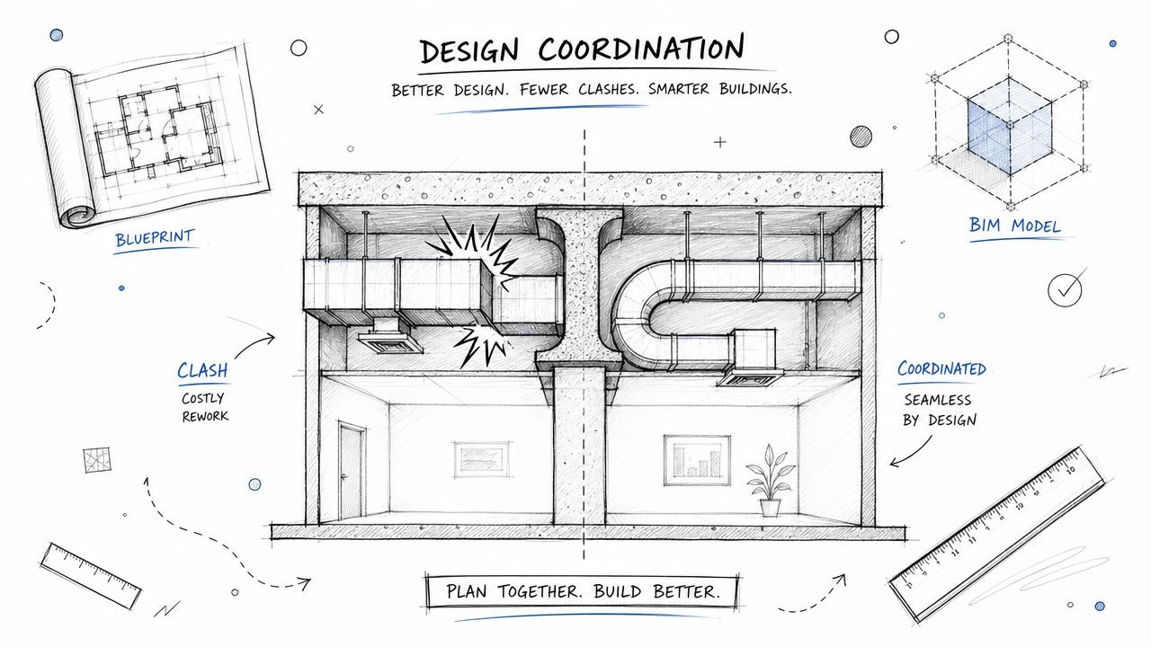
Coordinate early and often
Medical gas routing touches architecture, structure, electrical, headwalls, ceilings, equipment planning, and infection control constraints. That's why frequent model coordination matters more than heroic late cleanup.
Good clash detection doesn't just identify hard clashes. It catches access problems around valve boxes, maintenance conflicts in source equipment rooms, and ceiling congestion that makes terminal placement ambiguous. Teams using structured clash detection workflows tend to avoid the classic late-stage RFI cycle where med gas gets rerouted after headwall fabrication decisions are already moving.
For healthcare environments that are also tightening operational reporting, tools like an AI-powered safety platform for healthcare can add useful context around safety documentation and accountability, especially where facilities teams want clearer oversight after turnover.
Put QA checkpoints inside production, not after it
The teams that issue predictable healthcare sets don't wait until the end for quality control. They place decision checkpoints at the moments where errors are cheapest to fix.
A workable sequence looks like this:
Schematic checkpoint
Confirm source strategy, system list, major zones, and room-by-room clinical requirements.Mid-model checkpoint
Review routing logic, riser continuity, valve zoning, and room terminal counts against architectural layouts.Pre-sheet checkpoint
Validate family data, tag behavior, schedules, and detail callout consistency.Permit QA checkpoint
Review notes, cross-discipline panel locations, source equipment dimensions, and code references.Construction issue checkpoint
Confirm that final sheet output matches the coordinated model and that no annotation-only fixes broke the underlying logic.
BIM maturity shows up when the model prevents ambiguity instead of documenting it neatly.
Deliver a handover package facilities can actually use
An as-built model should help the owner locate source equipment, isolate zones, identify outlet types, and understand alarm coverage. If the final model is just a permit artifact, the team missed part of the value.
For hospitals and outpatient facilities, that matters long after closeout. Renovation teams will come back to these systems. If your handover package has clear zone intelligence and coordinated device data, the next project starts with usable information instead of a survey exercise.
The Pre-Submission QA Checklist for Medical Gas Drawings
Most bad permit comments on medical gas sheets are avoidable. They come from missing coordination steps, not exotic engineering issues. Before issuing a set, run a hard QA pass that treats the package like an inspector will.
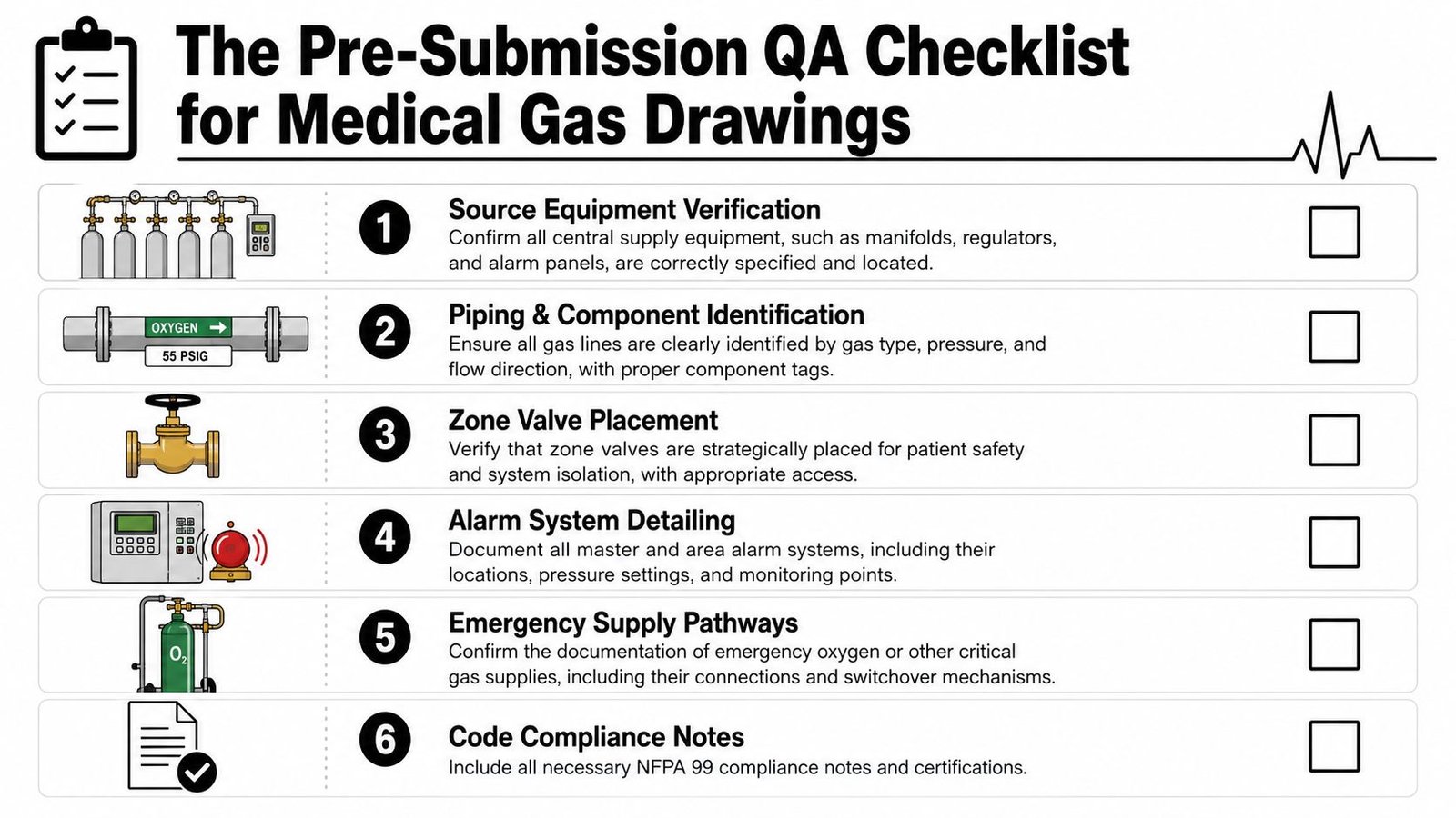
Pre-submission checks that catch the usual failures
Zone valve boxes shown and named
Add every zone valve box to the medical gas plan and identify the downstream zone it controls.Outlet counts verifiable by room
Show outlet symbols and quantities in each room with medical gas service so reviewers can confirm the count.Pipe sizes labeled throughout
Don't leave sizing to selective branches or risers. Label every segment of the distribution system.Source equipment setbacks dimensioned
Put setback dimensions on the site plan or equipment room plan so compliance isn't implied.Medical air intake and exhaust coordinated
Check these against windows, doors, and other intakes on the architectural sheets before issue.Alarm panels placed on the right sheets
Show master and area alarm panel locations with zone identification, including electrical coordination.Testing references included
Add the required NFPA 99 Chapter 5 testing reference note to the medical gas plan.
This checklist does more than prevent comments. It protects predictability. Every item you catch before permit or construction issue is one less field clarification draining fee and schedule.
Conclusion
The drawing set usually gets judged in the last week. The outcome gets decided much earlier, when the team chooses whether NFPA 99 will live only in notes or be built into the model, sheet setup, families, schedules, and QA process from day one.
Good medical gas documents give installers a clear path, give reviewers fewer reasons to reject the set, and give the project team fewer RFIs during fabrication and field coordination. That comes from production discipline. Source equipment is modeled and tagged consistently. Pipe sizing is carried through the full network. Alarm, valve, and outlet data matches across plans, risers, and schedules. QA checks happen before issue, not after comments come back.
That is the ultimate payoff.
Teams that translate code requirements into BIM standards and repeatable checking routines catch drawing deficiencies while they are still cheap to fix. Teams that wait until permit review usually pay for the same miss three times, in redesign time, review comments, and schedule pressure. In healthcare work, that is avoidable.
If your team needs stronger healthcare production workflows, cleaner medical gas system construction documents, or help scaling coordinated MEP delivery, contact BIM Heroes for MEP production support on healthcare projects. A good next step is reviewing their MEP services page and asking for templates, checklists, or a workflow conversation built around your current drawing standards.