Meta description: Plumbing isometric drawings are often the missing piece in commercial permit sets. Learn what they show, who owns the scope, when jurisdictions require them, and how disciplined CAD and Revit workflows prevent permit corrections.
The permit set looks complete until the correction notice lands. The plumbing plans are there. Fixtures are tagged. The drain and vent layout looks reasonable. Then the reviewer asks for plumbing isometric drawings, and the team discovers nobody owned them.
That gap shows up on commercial and multifamily work all the time. The architect assumes the MEP engineer included them. The MEP engineer assumes the plumbing contractor will handle them later. The contractor assumes they belong in the engineer's permit package. By the time someone sorts out responsibility, the submission is already stalled.
Production discipline is critical. Plumbing isometric drawings aren't just another drafting task. They're a permit risk item, a coordination checkpoint, and a simple test of whether scope was defined clearly enough at project start. When teams treat them as optional or defer them to “later,” they invite corrections, RFIs, and avoidable rework.
The Scope Gap That Delays Your Permit
The failure rarely starts with drafting. It starts with assumptions.
A project architect pushes a permit set toward issue because the floor plans look finished. The plumbing engineer has laid out the system in plan, but no one asked whether the jurisdiction wants isometrics or a plumbing riser diagram. The subcontractor isn't even under contract yet, so there's no chance they're producing permit-level diagrams. Everyone is working. Nobody is wrong on effort. The process is wrong.
That's why isometric drawings for plumbing should be treated as a scope ownership question before they become a document production problem. If the requirement isn't confirmed early, the set can move all the way to submission with a missing deliverable hidden in plain sight.
The most reliable teams handle this up front:
- Confirm jurisdiction requirements early: Check what the reviewer expects for DWV, venting, and domestic water representation before sheet production gets too far.
- Assign the deliverable in writing: Put plumbing isometric drawings in the engineer's scope or the trade's scope. Don't leave it implied.
- Put it on the permit QA checklist: If it isn't on the checklist, it usually gets discovered too late.
Field lesson: Permit delays often come from missing ownership, not missing effort.
What Plumbing Isometrics Actually Show
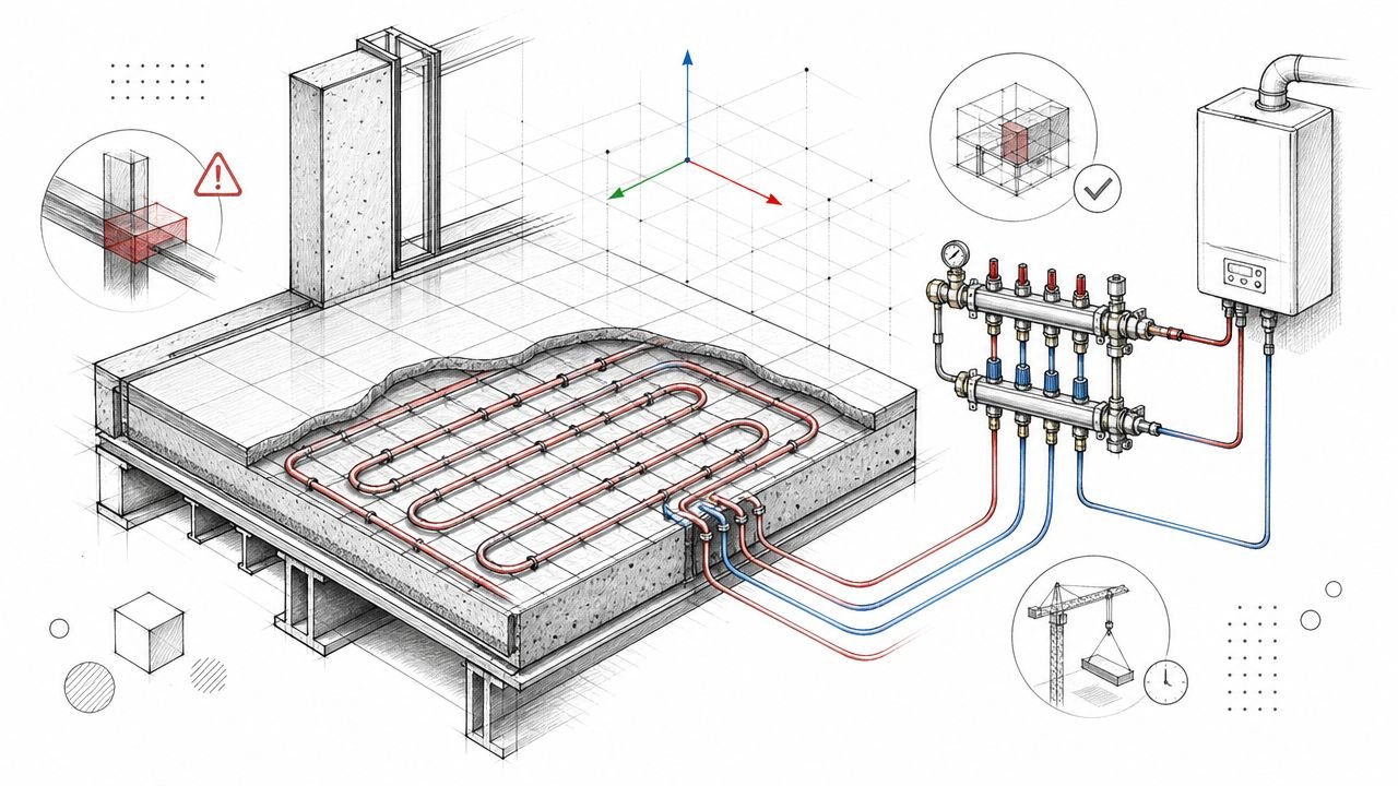
A plumbing isometric is a schematic. It shows system logic, not exact installed geometry.
Trade education has long treated isometrics as the practical way to turn plan information into a construction-friendly view, especially for DWV work, because they compress three-dimensional information into a single view and reduce the ambiguity that a flat plan can't resolve, as explained in this plumbing training reference on creating DWV plans and isometric drawings.
What it must show
For permit and review purposes, the isometric needs to make connectivity obvious. A reviewer should be able to trace the system without hunting across multiple sheets.
Typical required content includes:
- Pipe sizes on every segment: Not just mains. Short fixture branches matter too.
- Pipe material: The drawing should identify what system is being specified.
- Slope direction and slope rate: Horizontal drainage lines need explicit notation.
- Fixture connections: Each fixture tie-in should be readable and logically connected.
- Cleanouts, vents, and traps: These are review items, not optional drafting decoration.
- Connection to the building drain: The system has to resolve to the building drain and sewer path clearly.
What it does not show
Teams often misunderstand this point. A plumbing isometric is not there to prove exact coordination with structure, framing, or ceiling congestion. It is not a substitute for a fully coordinated model. It also isn't a scale section.
Think of it as a controlled abstraction. It shows topology, branch relationships, stack logic, vent paths, and the information a reviewer needs to understand whether the plumbing design works on paper.
A clean isometric tells the reviewer how the system behaves. A cluttered one forces the reviewer to interpret it.
That distinction matters because many bad permit drawings fail by trying to show too much. Once the isometric starts mimicking a model view instead of a schematic, clarity drops fast.
When Jurisdictions Mandate Isometric Drawings
This is the practical rule. If you're producing commercial or multifamily permit work, assume plumbing isometrics are on the table unless the jurisdiction clearly says otherwise.
Most jurisdictions applying IPC or UPC review standards expect a clear schematic for sanitary drainage and vent systems on commercial submissions. In many cases, domestic water may be handled with a riser rather than a full isometric, but that depends on local practice and amendments. That's why code family alone doesn't solve the question. The local submission standard still controls.
Where teams get caught
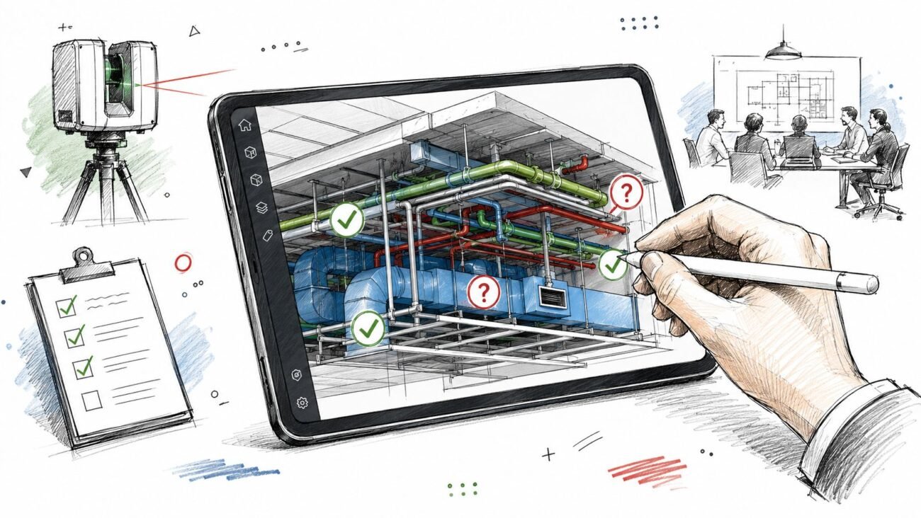
The common failure point is easy to recognize. The permit package includes a plumbing plan with fixture locations and rough routing, but no supporting isometric plumbing permit drawings. The set looks complete to the design team because the plans are there. The reviewer sees an incomplete code review package because the three-dimensional system logic is missing.
Project type usually tells you how cautious to be:
- Commercial projects: Expect sanitary and vent isometrics to be requested frequently.
- Multifamily projects: Reviewers often want clear vertical and branch logic because repeated unit layouts still create stacked system complexity.
- High-rise work: The burden is higher. Stack relationships and system continuity need to be unambiguous.
- Single-family residential: A plumbing plan may be enough in some jurisdictions, but that doesn't carry over to larger building types.
IPC and UPC aren't interchangeable in review practice
Teams that work across states need to stay disciplined here. IPC and UPC jurisdictions don't always ask for permit documentation in exactly the same way, and state or city amendments can shift what's accepted. The right move isn't to guess based on the last job. The right move is to confirm the local requirement at the beginning of document production.
If the written requirement is vague, produce the more complete deliverable. That usually means the isometric.
Who Owns the Isometric Production Scope
If ownership is fuzzy, the permit set is already at risk.
On projects with a licensed plumbing engineer of record, plumbing isometric drawings belong in the engineering scope. They're engineering documents. They support code review. They shouldn't be floating around as an unassigned future trade deliverable if they're needed for permit.
On architect-led projects where the architect carries plumbing design responsibility, the architect's team owns the outcome. That doesn't always mean drawing them in-house, but it does mean making sure they exist before submission.
The dangerous version of design-build
Design-build can solve this cleanly or make it worse. If the plumbing subcontractor is explicitly contracted to produce permit-level isometrics, fine. If the subcontract only mentions shop drawings or fabrication drawings later in the process, then the permit scope is still uncovered.
That's the difference between a managed handoff and a scope hole.
A disciplined scope assignment should answer three questions:
| Question | What needs to be decided |
|---|---|
| Who produces it | Engineer, architect-led production team, or plumbing trade |
| When it is due | Before permit submission, not after review comments |
| What standard applies | Permit schematic, coordinated BIM output, or fabrication-ready detail |
The process that actually works
The teams that avoid this problem don't rely on habit. They rely on checkpoints.
- Jurisdiction check at kickoff: Confirm whether isometrics, risers, or both are expected.
- Contract language: Name the deliverable directly in consultant or trade scope.
- Permit checklist gate: Don't issue without a yes or no against the requirement.
- QA ownership: One person should verify the sheet exists and is coordinated with the rest of the package.
Scope language protects schedule more reliably than last-minute drafting effort.
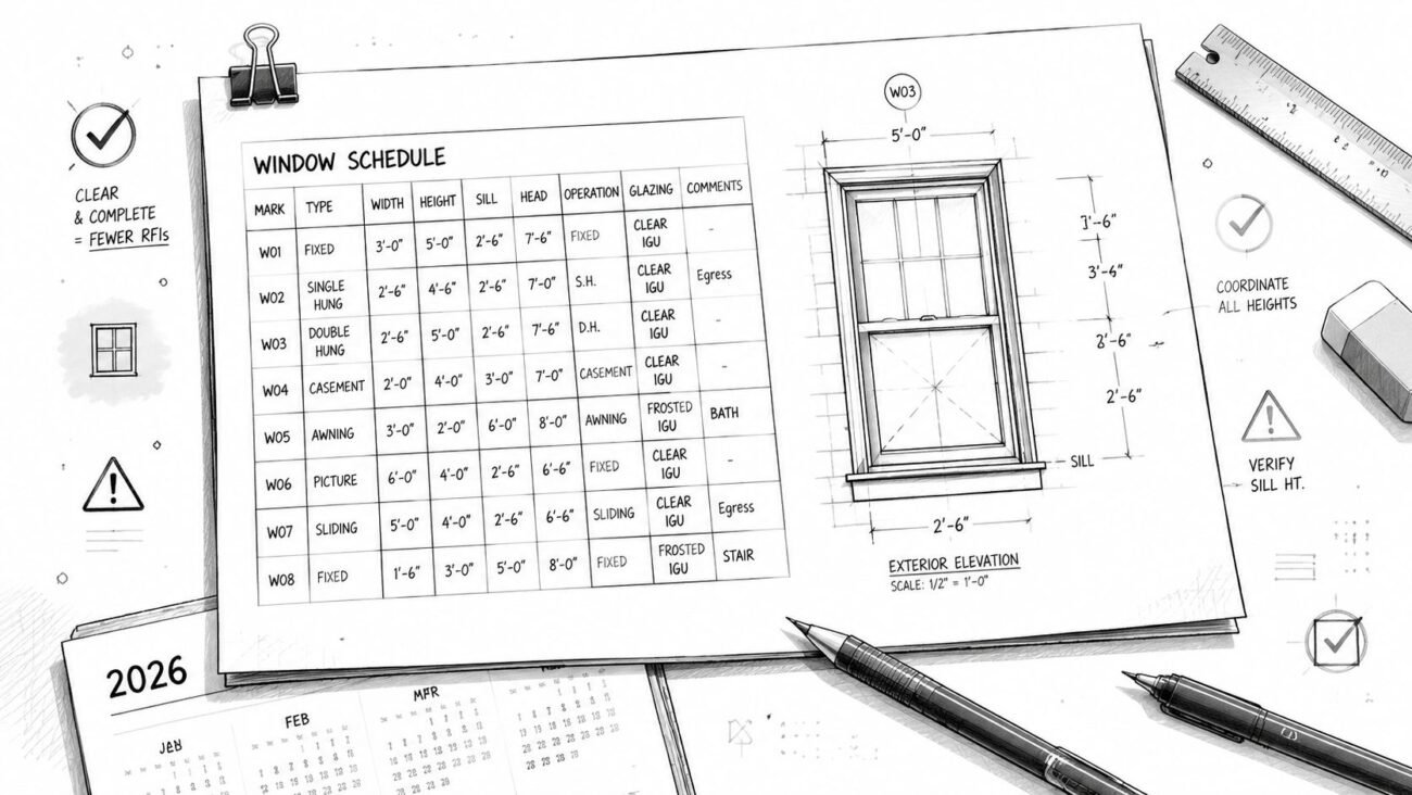
Your Checklist for Code-Compliant Isometrics
Most permit corrections on plumbing isometrics are predictable. The reviewer is looking for a short list of required items, and the drawing either answers those questions or it doesn't.
For production-quality isometrics, directional accuracy is a hard control. Training guidance for plumbers treats the drawing like a road map. Orientation and flow direction are explicitly checked, and one error in fixture placement or compass direction can invalidate the drawing, as noted in this plumbing isometric training video.
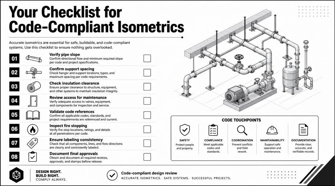
The non-negotiable content
If your team is producing permit or shop-level plumbing documents, this review logic should look familiar. It aligns closely with the same controls used in plumbing shop drawings workflows, where missing tags or disconnected notation create downstream confusion fast.
Use this as a pre-submission checklist:
- Pipe size on every segment: Reviewers don't assume continuity. Every branch, offset, and short connection needs a visible size.
- Pipe material identified: The isometric should state what material applies to the line type shown.
- Slope called out on horizontal drainage: Don't leave slope implied. Label it where the reviewer reads it.
- Fixture loading shown clearly: Fixture connections need to be legible enough for sizing review.
- Cleanouts placed and tagged: If they're missing from the isometric, the reviewer will assume they're missing from the design logic.
- Vent paths resolved: Show how vents connect and where they terminate.
- Traps and relevant distances noted: Especially where trap arm length is close to code limits.
What reviewers reject first
The worst errors aren't artistic. They're geometric and informational.
A branch that runs the wrong direction. A flow path with no arrow. A fitting omitted at the point the line changes direction. An offset that breaks the isometric grid. A fixture tied in without enough information to verify sizing. Those are the failures that trigger comments because they make the drawing unreliable.
A usable QA sequence
The review should happen in order, not as a random markup session.
- Set orientation first: North, south, east, west, and up/down need to be stable.
- Trace the main run: Confirm the core path before checking branches.
- Review each branch connection: One by one, fixture by fixture.
- Check annotations last: Sizes, slope, labels, material, and flow direction.
Practical rule: If a reviewer has to infer a critical condition, the isometric is not finished.
Riser Diagram vs Full Isometric Drawing
A riser diagram and a full isometric aren't the same deliverable, and treating them as interchangeable causes avoidable permit trouble.
A plumbing riser diagram is usually an elevation-style schematic. It's useful for showing vertical continuity, floor-by-floor connections, and stack relationships. It works well for domestic water systems and can be acceptable for simpler situations where the jurisdiction doesn't need a full three-dimensional schematic.
A full isometric carries more information. It shows the vertical runs, horizontal branches, and directional changes in one coordinated view. That gives the reviewer a much clearer understanding of drainage and vent relationships.
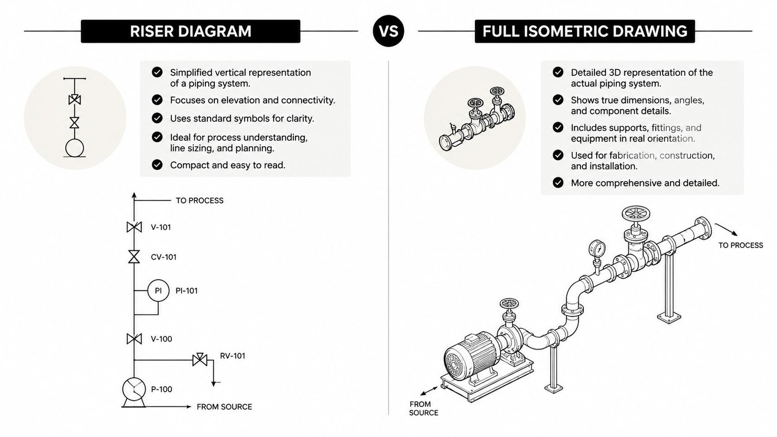
The distinction matters downstream too. If the project is moving toward fabrication, coordinated handoff, or spool development, the richer document usually creates fewer interpretation gaps. That's why teams working toward spool drawings generally benefit from carrying more structured system information earlier.
The safer decision
If the authority having jurisdiction says riser diagram, provide the riser. If they say isometric, the riser is not a substitute.
If the requirement is unclear, issue the isometric. It exceeds the riser in communicative value and usually prevents the back-and-forth that comes from giving the reviewer the minimum possible interpretation of the system.
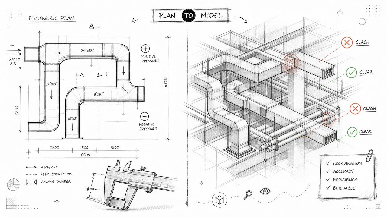
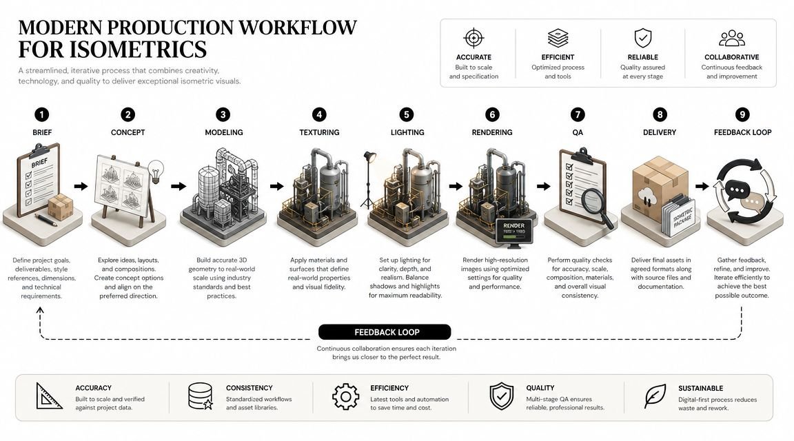
Modern Production Workflows for Isometrics
How a team produces plumbing isometric drawings tells you a lot about its production maturity. The method affects update risk, coordination quality, and how well the drawing survives design change.
A major gap in most tutorials is the handoff problem. They explain drawing conventions, but not what information an isometric needs if it will feed a coordinated model, fabrication spool, or material takeoff. That gap matters because information quality directly affects downstream installability and cost, as discussed in this isometric drawing reference focused on model and fabrication handoff.
Method one with manual 2D CAD
This is still common in offices that draft plumbing in AutoCAD. A drafter builds the isometric from plan views, sections, and design notes using isometric snap settings and manual annotation.
It works, but it's fragile. Every design revision creates a synchronization problem. If the plan changes and the isometric doesn't, the permit set now contains two truths.
Manual CAD is usually acceptable when the project is simple, the team is disciplined, and revision traffic is low. It becomes expensive when the set is still moving.
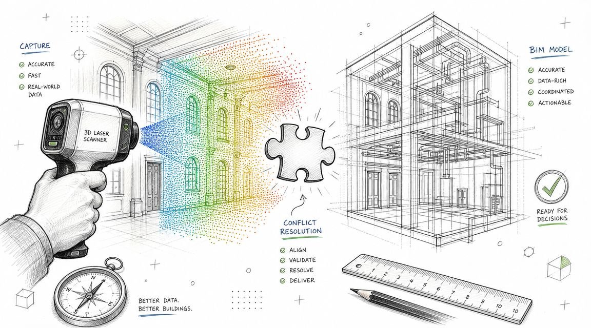
Method two with a Revit-based workflow
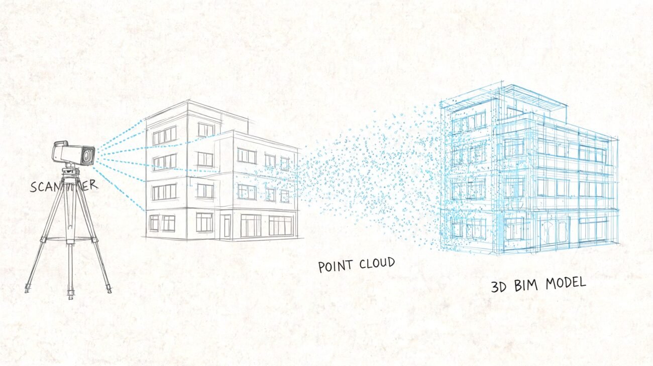
This is the strongest path when the plumbing system is modeled correctly. A plumbing isometric drawing Revit workflow can start from a Revit MEP model with pipe sizes, slopes, fittings, and fixture connectivity already embedded.
The catch is that Revit's native 3D isometric views often look too literal for permit use. They can be visually cluttered, hard to annotate, and loaded with geometry that a reviewer doesn't need. The better workflow is usually model-based extraction into a cleaner schematic presentation, whether through controlled view templates, detail overlays, or add-ins built for piping documentation.
Teams modeling domestic distribution and drainage in integrated MEP environments also get a cleaner path into related outputs like hot and cold water systems documentation, where consistency in tags, routing logic, and system naming matters across sheets.
Method three with schematic overlay outside the model
Some firms model in Revit, then draft the permit isometric separately in AutoCAD or Bluebeam after the model is done. This can feel efficient because the model gives the drafter a visual reference.
The problem is still disconnection. Once the isometric becomes a separate graphic artifact, it no longer updates with the model. The workflow is faster than pure manual drafting from scratch, but it inherits the same coordination risk.
Clean production doesn't just create the sheet. It preserves trust between the sheet and the model.
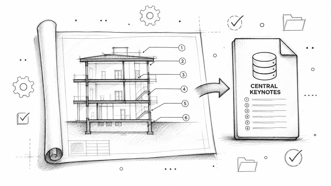
What mature teams standardize
The best-performing documentation groups standardize more than software. They standardize decision points.
- Template logic: Consistent annotation, pipe tags, and view setup
- LOD expectations: Enough model information to support extraction
- QA sequence: Model check first, sheet check second
- Revision control: Clear responsibility for updating the isometric when design changes
That's what turns isometrics from a recurring fire drill into a stable part of MEP construction documents plumbing workflows.
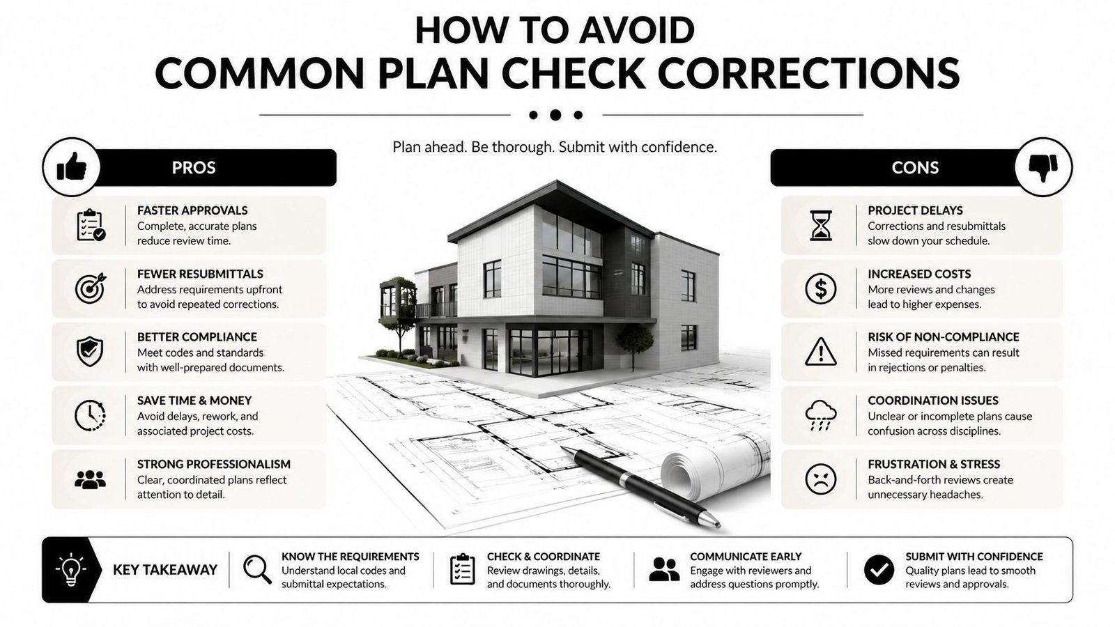
How to Avoid Common Plan Check Corrections
Most plumbing review comments are repetitive. That's good news because repetitive problems can be prevented with a disciplined preflight.
Most online advice explains how to draw an isometric, but it often misses the harder question of how to verify that the drawing is code-compliant and buildable. That matters most on complex DWV layouts, where errors hide in the three-dimensional path and show up later as rework, as discussed in this advanced plumbing isometric article.
The self-audit before issue
Run this check before the package leaves your desk:
- Verify every pipe segment is tagged: Missing labels often hide on short fixture connections and branch stubs.
- Check slope annotation on each horizontal drain: If it matters to drainage, label it.
- Confirm fixture loading information is present where needed: The reviewer has to be able to follow sizing logic.
- Review cleanout placement against the governing code: Don't rely on memory.
- Show vent termination clearly: The roof termination should read without guesswork.
- Add material notes: If the pipe type changes by system, say so directly.
What usually slips through
The mistakes are rarely complicated. One unlabeled branch. One missing cleanout. One vent line that stops just below the roof line on the sheet. One material note that exists on the plan but not on the isometric. Those are small misses with real schedule consequences.
A sharp internal QA pass should catch them before the city does.
From Drawings to Predictable Delivery
Strong plumbing isometrics do more than satisfy a reviewer. They expose whether the team has a repeatable production system.
When scope is assigned early, templates are controlled, and QA checks are real, plumbing isometric drawings stop being a surprise deliverable. They become part of a predictable permit workflow. That protects margin, reduces avoidable RFIs, and keeps coordination effort focused where it belongs.
Firms don't need more heroic last-minute drafting. They need better production habits, better ownership rules, and documentation standards that hold under revision.
If your team needs help standardizing MEP production, cleaning up permit workflows, or building reliable documentation systems around plumbing and BIM coordination, BIM Heroes can support that effort. Reach out if you want practical help with templates, QA checklists, or MEP production support that keeps delivery predictable.