Meta description: Scan to BIM projects usually fail at the process level, not the scan itself. Learn the five mistakes that drive cost overruns, rework, and handoff delays in scan to bim services.
The popular advice about scan to bim services is usually wrong. It treats bad outcomes like a hardware problem, a software problem, or a staffing problem.
Most of the time, it's none of those.
Projects go sideways because teams leave the critical decisions vague until after field capture, after modeling starts, or worse, at handoff. By then, the expensive part has already happened. The scanner may have done its job. The modeler may have worked hard. The PM still ends up with a model that can't support coordination, permitting prep, or reliable downstream documentation.
That's why the firms that get consistent results don't just buy scanning. They run a controlled production workflow.
The Hidden Failures That Derail Scan to BIM Projects
Scan to BIM is growing fast, but market growth doesn't equal delivery maturity. The global Scan-to-BIM Service market was valued at $1.2 billion in 2024 and is projected to reach $4.3 billion by 2033, according to Market Intelo's Scan-to-BIM Service market report. At the same time, the same verified data notes that 68% of US AEC firms under 50 employees cite unclear pricing as the top barrier to adoption.
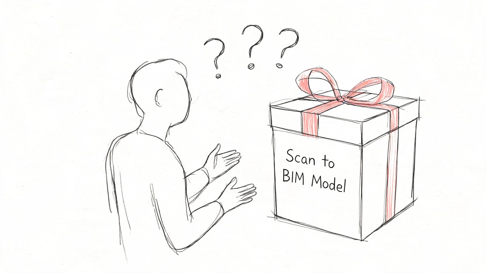
That combination matters. Demand is expanding, but many buyers still don't trust the process.
The reason is familiar to anyone who has inherited a broken as-built model. The failure usually starts before anyone opens ReCap or Revit. It starts in the brief, in the scope, in the coordinate strategy, in the LOD assumptions, and in whether anyone defined an actual QC gate. If those decisions are loose, the project becomes unpredictable even when the point cloud itself looks clean.
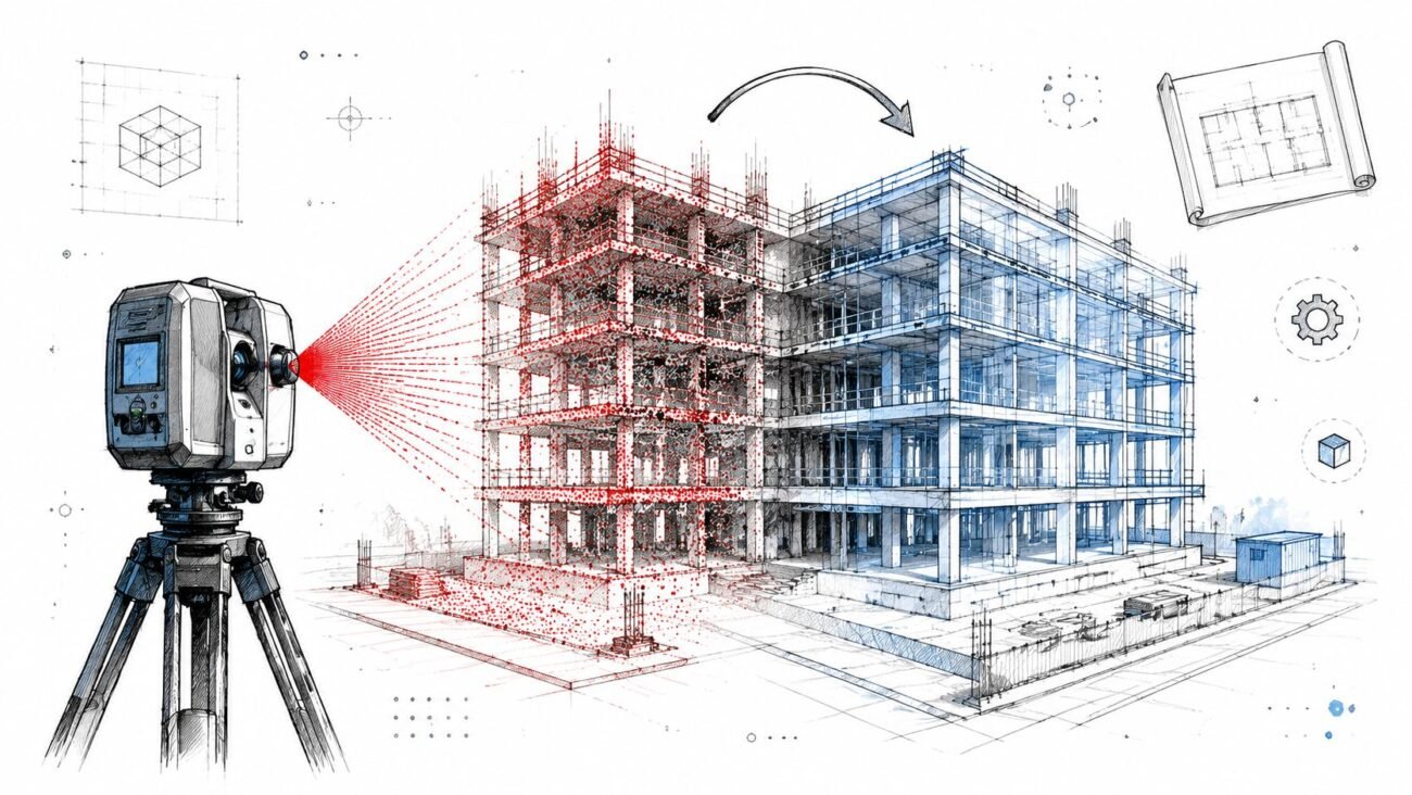
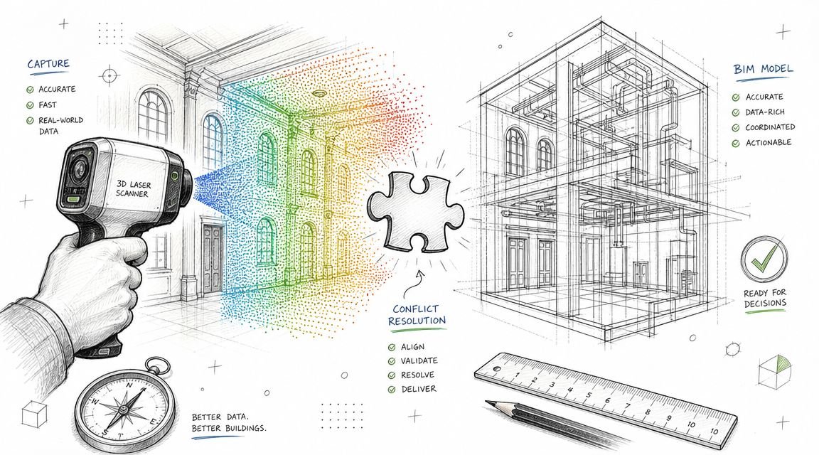
A reliable team treats scan to bim services as a production system, not a one-off technical task. That means disciplined intake, documented checkpoints, and a handoff standard that design teams can trust. A strong reality capture workflow does exactly that. It turns field data into usable model data without forcing the architect, engineer, or contractor to absorb hidden cleanup later.
Most scan to BIM failures are management failures wearing a technical disguise.
Mistake 1 Specifying the Wrong Scan Density for the LOD
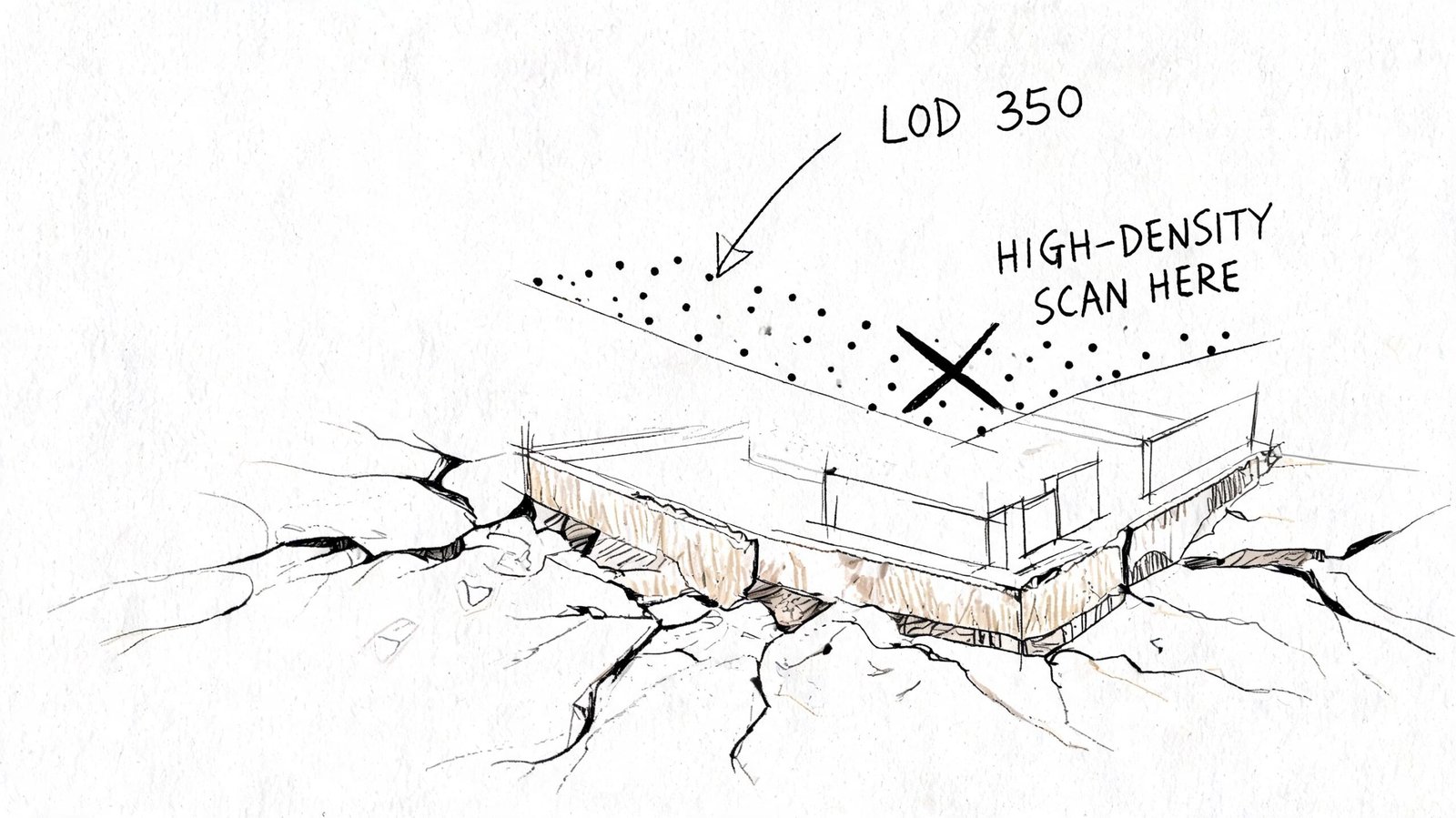
This is the earliest mistake, and it contaminates everything downstream.
Teams often write “perform laser scan and create BIM model” as if field capture is a generic input. It isn't. Scan density determines whether the modeler has enough information to build the required geometry with confidence. If the deliverable is a simple architectural as-built, the capture strategy can be lighter. If the deliverable includes congested MEP zones, connection points, steel profiles, or equipment clearance validation, the scan strategy has to support that level of detail.
What goes wrong in practice
The common failure is that the scanning vendor chooses density based on field convenience, while the BIM team is pricing and modeling against a different expectation. That disconnect is expensive.
Per VIBIM Global's Scan to BIM cost guide, Scan-to-BIM project costs can range from $0.50 to over $10.00 per square foot. The same source notes that under-scanning may require re-mobilization fees starting at $2,000-$10,000, while over-scanning can inflate the 40+ hours of modeling labor common on mid-sized projects.
Under-scanning creates guesswork. The modeler starts tracing edges that aren't clearly readable, fills gaps from judgment, and pushes uncertainty into QC. If the missing detail sits in an equipment room or above-ceiling MEP zone, the project either pays for another site visit or accepts a model that shouldn't be trusted.
Over-scanning creates a different problem. The team captures more data than the intended use requires, then drags oversized point clouds through ReCap, Revit, coordination, and archive storage. That looks thorough on day one and wasteful by day ten.
What a proper requirement looks like
A useful scope doesn't ask for “high accuracy.” It defines scan intent by discipline and deliverable. It ties field capture to the model purpose.
Use this as a minimum brief structure:
- Project use case. Renovation design, MEP coordination, permit set support, facilities record model, or heritage documentation.
- Element-level priority. Walls and slabs aren't the same as duct branches, equipment, or structural connections.
- Required LOD by category. The BIM Level of Detail guide should inform this before the scanner is scheduled.
- Occlusion risks. Above-ceiling zones, tight risers, plant rooms, and crowded service corridors need explicit planning.
- Deliverable tolerance expectations. If the model must survive coordination review, the field capture has to support that.
What works and what doesn't
| Situation | What works | What fails |
|---|---|---|
| TI interior as-built | Density aligned to architectural geometry and openings | Applying MEP-heavy capture logic everywhere |
| MEP retrofit | Capture planned around congested services and hidden conditions | Treating ceiling spaces as optional |
| Structural as-built | Prioritizing member shape, intersections, and bearing conditions | Assuming broad room scans are enough |
| Heritage documentation | Extra attention to irregular geometry and surface variation | Using generic settings meant for standard commercial interiors |
Practical rule: If the field team can't explain why the chosen density supports the required LOD, the project isn't ready to scan.
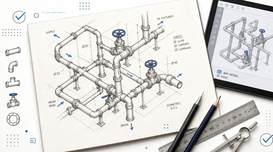
Mistake 2 Skipping Shared Coordinate Setup Before Modeling
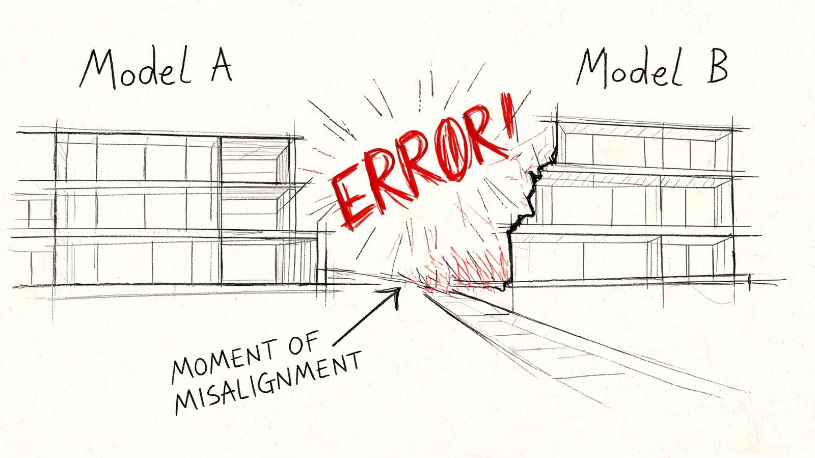
This mistake remains hidden until the team tries to use the model for real work.
A point cloud can look perfect in isolation and still be useless in a project environment. The usual pattern is simple. The scanner captures to its own local setup. The point cloud gets processed. The BIM team imports it and starts modeling. Weeks later, someone links the as-built into the live design file and finds the model rotated, offset, or sitting at the wrong elevation.
At that point, nobody cares that the walls were traced cleanly. The model is sitting on the wrong datum.
Why this breaks projects
The core issue is registration and coordinate control. According to Designing Buildings' technical guide to Scan to BIM workflow and deliverables, point cloud registration requires 30-50% overlap between scans. The same source notes that poor registration can introduce positional errors up to 5-10 cm, which then increase rework by 15-20% in complex renovation projects through downstream clash failures.
That's the technical side. The production side is even more painful. If the point cloud wasn't tied correctly to shared coordinates before modeling, every modeled element inherits the wrong frame of reference. Doors, walls, ceilings, equipment, grids, and levels may all be internally consistent and still be unusable when linked with civil, structural, or live design files.
The non-negotiable setup sequence
Before modeling starts, the team needs a written coordinate plan. In practice, that means:
- Survey control is defined on site and made available to the capture team.
- Registration in ReCap or equivalent software references that control instead of relying on an arbitrary origin.
- Revit shared coordinates are established first, not after geometry is modeled.
- Project Base Point, Survey Point, and orientation strategy are checked against the receiving project environment.
- A live link test is done before production ramps.
A coordinated BIM execution plan should lock this down before any production model leaves kickoff.
True north and project north both matter
Teams sometimes dismiss orientation as a cleanup task. It isn't.
True north matters for site alignment, survey relationship, and external references. Project north matters for sheet logic, working views, and internal production consistency. If the scan-to-model workflow ignores one of them, someone later has to choose between a model that coordinates correctly and a model that documents cleanly. That's a bad trade to make after modeling is complete.
A model built on the wrong coordinates isn't “almost done.” It's often a reset disguised as progress.
Mistake 3 Mismatching LOD Expectations Between Client and Modeler
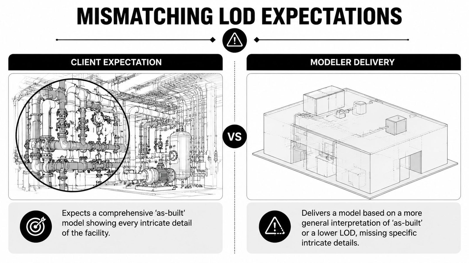
This is usually blamed on modeling quality. It's usually a scope failure.
“As-built model” sounds precise until two teams use it in the same meeting. The PM may mean a dependable model for coordination and downstream design. The modeler may mean a geometric representation suitable for planning layouts. Both think they're being reasonable. Both leave the kickoff thinking alignment exists. The conflict appears at review.
Where the mismatch shows up
The problem isn't abstract. It appears in very specific category decisions:
- Pipes shown as centerlines when the design team expected outside diameter representation.
- Mechanical equipment modeled as simple boxes when the team needed recognizable families and connection logic.
- Structural steel represented as simplified members when the intended use required actual profile interpretation.
- Ceilings and soffits modeled broadly while the architect expected enough fidelity for renovation documentation.
- Openings captured geometrically, but not classified in a way that supports schedules or coordination.
None of those are “bad modeling” by themselves. They become bad delivery when the required LOD was never stated by category.
What to write into the scope
A serious scope of work includes an LOD matrix. Not a sentence. Not a slide. A matrix.
That matrix should define:
| Element category | Expected development | Information needed | Responsible party |
|---|---|---|---|
| Architectural shell | Geometry sufficient for planned use | Key parameters and host behavior | Modeler or design team, depending on scope |
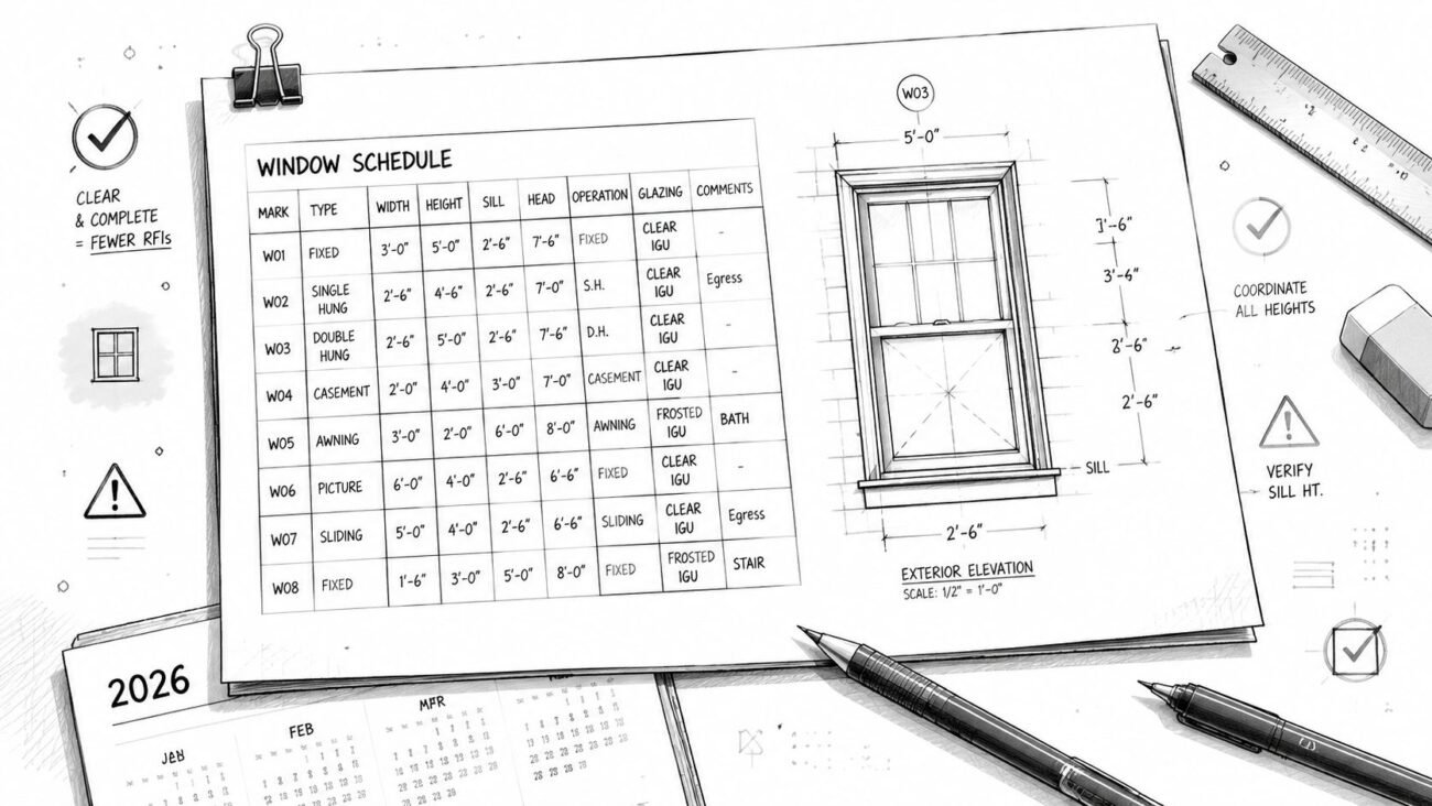
| Doors and windows | Category-correct objects | Schedulable data if required | Defined at contract stage |
| MEP distribution | Representation style agreed in writing | Coordination intent stated clearly | Shared decision between PM and BIM lead |
| Equipment | Family approach and connection expectations | Naming and metadata expectations | Defined before production |
| Structural framing | Simplified or profile-based logic | Use case tied to coordination or documentation | Locked before modeling |
If that sounds basic, that's because it is. Yet many scan to bim services projects still begin with “model the building from the scan” and little else.
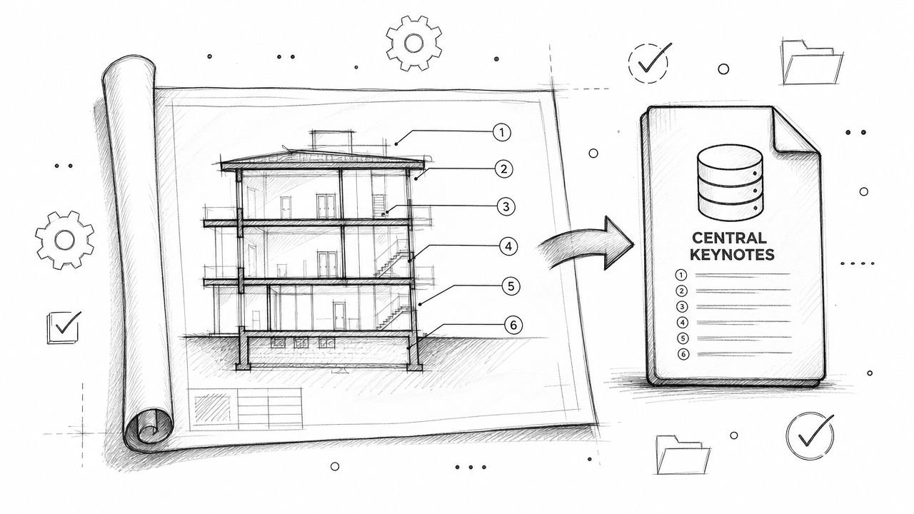
Use a recognized framework, then make it project-specific
The right move isn't to invent your own vocabulary in kickoff meetings. Use a standard reference such as the BIMForum LOD Specification to anchor the discussion, then convert that into project language by category, use case, and model ownership.
If the contract doesn't define what “done” looks like, QC becomes an argument instead of a checkpoint.
The discipline here protects both sides. The client gets a model fit for purpose. The modeler gets a scope that can be priced, planned, and staffed without hidden assumptions.
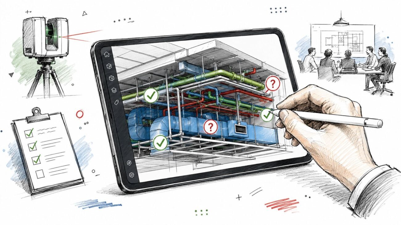
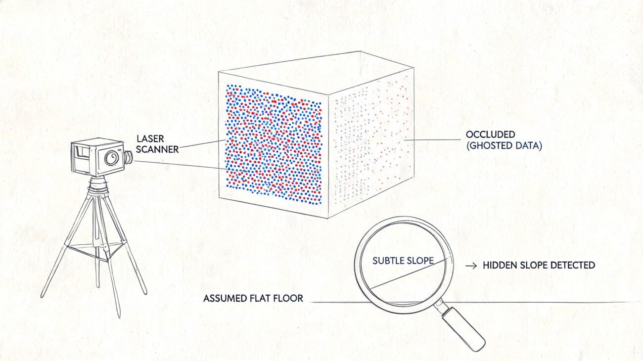
Mistake 4 No QC Process Between Point Cloud and Model Delivery
A visual spot-check is not QC. Rotating a 3D view and saying “looks right” is not QC. Opening schedules and hoping they populate is not QC.
A professional QC gate compares the model to the point cloud, verifies category behavior inside Revit, and checks that the deliverable can support the workflow it was commissioned for.
What a real QC pass includes
Per Techture's introduction to scan to BIM and laser scanning, a proper QC process verifies the model against the point cloud with tolerances of ±5 mm for architecture and ±10 mm for MEP. The same source states that cloud-to-model deviation heatmaps and validation that automated segmentation achieved 95%+ accuracy for LOD 300 elements are key steps that cut downstream clash resolution time by up to 40%.
Those numbers only matter if the team uses them as a control gate, not as marketing language.
A practical QC review should test at least four things:
- Category integrity. Walls should be walls, floors should be floors, ceilings should be ceilings. Generic Models are often a warning sign that production speed was prioritized over usable output.
- Geometric compliance. Deviation checks against the point cloud should confirm the model stays within the agreed tolerance.
- Completeness. Thin scan areas, occluded zones, and skipped elements need to be identified and reported, not quietly ignored.
- Model usability. Schedules, parameters, levels, and grids need to function in the receiving environment.
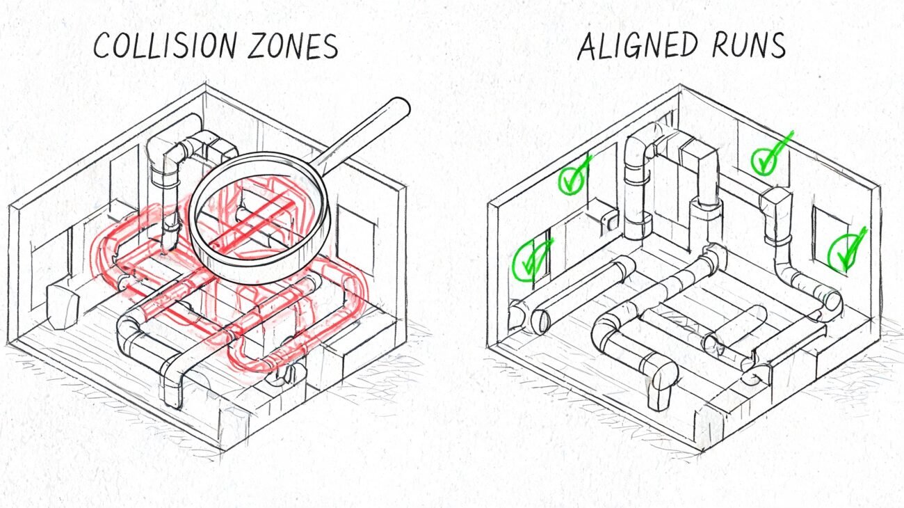
The failures that show up later
The worst QC misses don't always appear on handoff day. They appear when the architect starts laying out new walls, when the MEP engineer runs coordination, or when the contractor exports for clash review in Navisworks.
Typical late-stage symptoms include:
- Bloated files caused by embedded junk geometry or unmanaged links.
- Broken schedules because model categories or parameters were handled inconsistently.
- Coordination noise because levels and grids don't align to the broader project environment.
- False confidence because the geometry looks believable but hasn't been validated against the cloud.
Bad as-built models don't stay isolated. Design teams build on top of them, and construction teams pay for the errors later.
What the handoff should include
A proper delivery should come with documentation, not just files. At minimum, ask for:
- Tolerance verification summary
- Cloud-to-model deviation evidence
- Element count or category completeness check
- Schedule and parameter validation
- Notes on exclusions, occlusions, and unresolved conditions
That's the difference between a commodity model and a dependable production asset.
Mistake 5 Wrong File Format or Software Version Handoff
This is the last-mile failure. It shows up after the work is “finished” and still manages to stop the job.
The most common example is a Revit version mismatch. The vendor builds in one version. The receiving firm is standardized on an older one. Revit doesn't support a clean backward save, so the handoff turns into a scramble of exports, workarounds, relinking, and preventable frustration.
The same pattern appears with point cloud packaging. A team may expect a unified file structure and receive something different. Or they receive a format that requires extra conversion time no one planned for. Or the model arrives with linked dependencies missing from the transmittal, so the opening view looks fine on the sender's machine and broken on everyone else's.
The checklist that prevents most handoff pain
This doesn't require new software. It requires five written decisions before production starts.
- Authoring platform alignment. Confirm the exact Revit version the receiving team needs.
- Point cloud packaging. State whether the team expects .RCP, .RCS, E57, or a combination, and who is responsible for conversion.
- Linked file rules. Define whether linked CAD, Revit, or point cloud references will be delivered, embedded, detached, or stripped.
- Coordinate confirmation. Require the model and cloud to open in the same agreed coordinate framework.
- Naming and transmittal conventions. Folder structure, file names, and issue logs should be fixed before the first model is published.
What to ask before you approve kickoff
A short technical alignment note is enough if it's specific. Ask these questions:
| Question | Why it matters |
|---|---|
| Which Revit version will the model be authored in? | Prevents unusable native files |
| What point cloud format will be delivered? | Avoids unplanned conversion work |
| Are all linked dependencies included? | Prevents broken references |
| Has shared coordinate alignment been tested in the receiving environment? | Avoids manual repositioning later |
| What is the folder and file naming standard? | Keeps handoff controlled and traceable |
This is also where many teams discover they never defined whether the final delivery is meant for active design authoring, archive, coordination, or owner record use. Those are different handoff targets. They need different packaging discipline.
A clean handoff doesn't feel dramatic. The files open, the links resolve, the cloud aligns, and the receiving team gets to work.
From Mistakes to a Reliable Scan to BIM Process
These five failures all point to the same conclusion. Scan to BIM projects don't usually break because the scanner was inaccurate or the software was inadequate. They break because nobody enforced the decision checkpoints that protect scope, geometry, interoperability, and quality.
A stable workflow is much less exciting than most marketing copy. It defines scan density in the brief. It locks coordinates before modeling. It writes LOD expectations into a matrix. It runs QC against the cloud before delivery. It confirms file versions and handoff standards at kickoff.
That's not bureaucracy. It's margin protection.
The firms that do this well don't rely on heroic recovery late in the job. They build predictability into the workflow early, then repeat it across projects, teams, and delivery pods. If you're evaluating vendors, reviewing a current model, or tightening your internal process, it also helps to compare expected outputs with Scan to BIM Deliverables, define scope using How to Write a Scan to BIM Scope of Work, and pressure-test the basics against a plain-English What Is Scan to BIM reference.
If you need a team that treats scan to bim services as a controlled production workflow, not a loose modeling task, BIM Heroes is a good place to start. We help AEC firms build reliable delivery from scan brief through QC-verified handoff. If you want a practical checklist, a scope framework, or a second look at a project that's drifting, reach out.