A submittal lands in the project manager's inbox late in the afternoon. The title block references an old architectural revision, the millwork elevations don't show the adjacent sprinkler zone, and the dimensions stop just before the condition that matters in the field. The contractor needs a review, the fabricator is waiting to release material, and everyone knows the next step could be an RFI.
That situation isn't caused by a lack of drafting software. It's usually caused by a weak production system, unclear responsibility, or a shop drawing that treats design intent and fabrication methodology as the same thing. A disciplined architectural shop drawing workflow separates those responsibilities, preserves the design record, and gives each reviewer a clear decision to make.
For firms that need additional production capacity, the same principles apply whether the work is completed internally or through an outsourced BIM/CAD pod. The objective isn't to produce more sheets. It's to deliver a traceable, coordinated package that protects margin, keeps review cycles predictable, and gives trades information they can build from.
Where Architectural Shop Drawings Sit in a Project
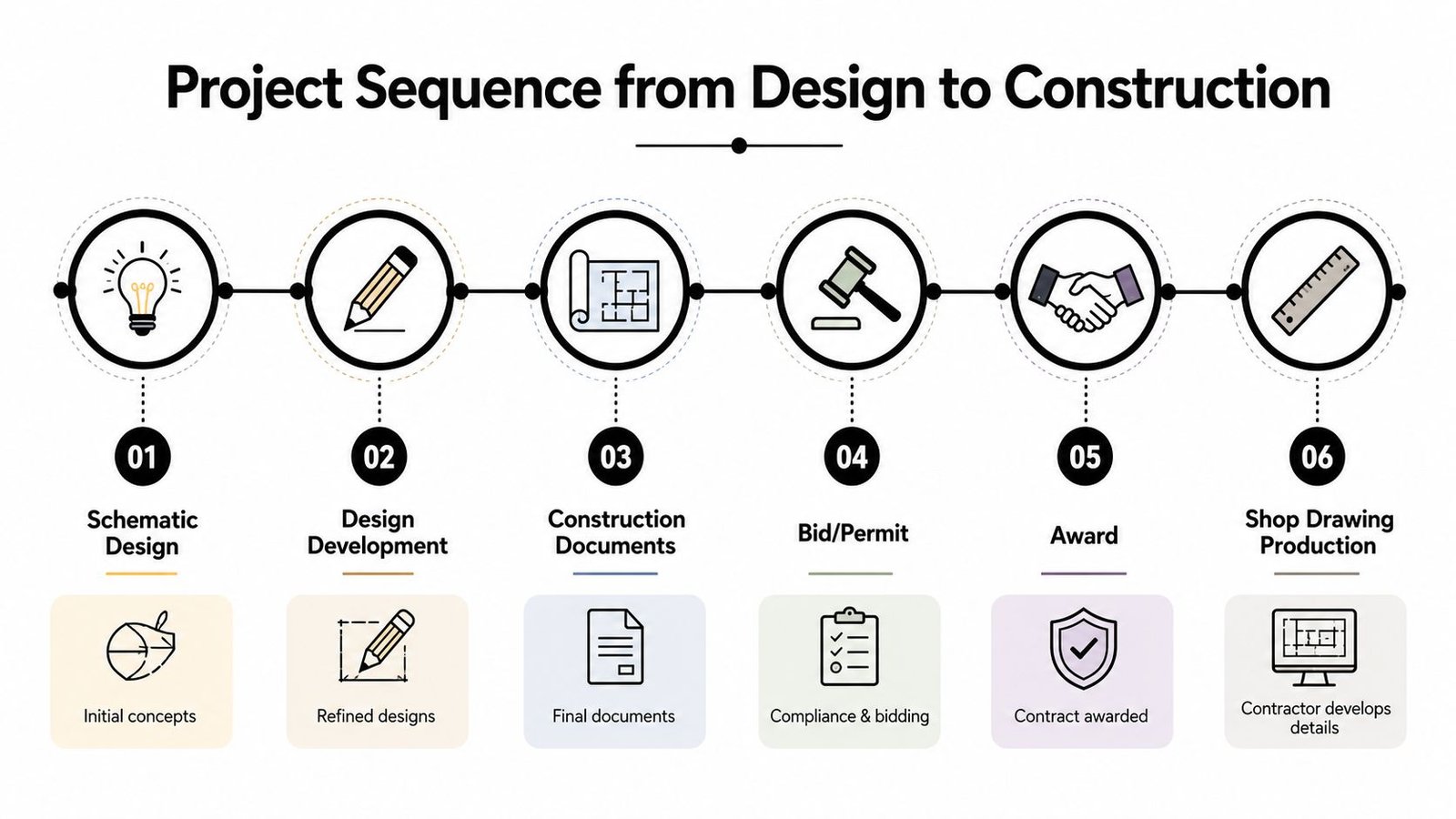
Architectural shop drawings appear after the design team has established the project requirements and the contractor or trade partner has taken responsibility for translating those requirements into fabrication-level information. Schematic design develops into design development, then construction documents. Those documents support bidding and permitting. After award, contractors, subcontractors, fabricators, and suppliers develop the detailed submittals needed for procurement, fabrication, assembly, and installation.
The issued-for-construction set remains the reference for design intent. The shop drawing adds the information required to execute a particular scope, such as exact dimensions, product-specific details, attachment conditions, material references, and interfaces with surrounding work. It doesn't replace the contract documents, and it shouldn't revise them.
A practical project sequence looks like this:
- Design development: The team resolves the building's systems, layouts, materials, and major interfaces.
- Construction documents: The architect and consultants issue the coordinated design package for bidding and permitting.
- Award and trade procurement: The contractor engages specialty trades, manufacturers, and fabricators.
- Submittal preparation: The responsible trade develops architectural shop drawings from the current contract set, approved products, and field information.
- Review and response: The contractor reviews first, then routes the package to the design professional for the contractually defined review.
- Fabrication and installation: The approved or appropriately noted information guides production, while field conditions and authorized changes continue to be documented.
- As-built record: The project team records what was installed for turnover and future maintenance.
RFIs should resolve ambiguities that the contract documents don't answer. They shouldn't become a substitute for basic shop drawing coordination. A strong submittal identifies the question, deviation, or interface before fabrication, while the submittal log records who reviewed it and what status governs the next action.
By the end of this guide, a production lead should be able to distinguish design intent from means and methods, specify what belongs on each sheet, structure a BIM or CAD workflow, and give the team a coordination checklist that supports tighter reviews, fewer avoidable RFIs, and clearer fabrication packages.
What an Architectural Shop Drawing Actually Is
An architectural shop drawing is a contractor-, subcontractor-, fabricator-, manufacturer-, supplier-, or distributor-prepared document that illustrates a specific portion of the work. Under the AIA A201-2017 framing, that can include drawings, diagrams, schedules, models, and related data prepared specifically for the work. The practical definition is simple: the document shows how a defined scope will be fabricated, assembled, or installed.
That distinction matters because the construction documents and shop drawings answer different questions. The construction documents establish what the design team requires. The shop drawing explains how a trade proposes to deliver a particular component within those requirements.
The definition of shop drawings is useful as a reference point, but production teams need a sharper operational boundary.
Practical rule: The design team defines the required result. The contractor and trade partners develop the implementation details, then remain responsible for their own fabrication and installation information.
The three documents people confuse
| Document Type | Owner or Author | Primary Purpose | Level of Detail |
|---|---|---|---|
| Construction Documents | Architect and engineering consultants | Communicate design intent, support bidding, and support permitting | Project-wide design and specification information |
| BIM Models | Architect, engineers, contractor, or specialty trades | Coordinate geometry, information, quantities, and documentation | Varies by author, scope, contractual requirements, and model use |
| Architectural Shop Drawings | Contractor, subcontractor, fabricator, manufacturer, supplier, or distributor | Direct fabrication, assembly, and installation for a defined scope | Product- and assembly-specific detail |
A BIM model isn't automatically a shop drawing. A design model may communicate intent, while a fabrication model may contain production information. The model becomes part of a shop drawing workflow only when the contract, submittal process, and responsible trade assign it that role.
AIA A201 §3.12 and RFI procedures become operational here. The trade prepares the submittal, the contractor performs its required review, and the design professional reviews within the contractually defined scope. If a proposed condition changes the design, the team needs a documented response rather than an informal adjustment hidden inside a detail.
For outsourced BIM or CAD production, that distinction should appear in the scope of work. The production team can extract views, develop details, coordinate interfaces, and prepare the issue package. It shouldn't be represented as the party assuming the contractor's means-and-methods responsibility or the architect's design responsibility.
What Goes on the Sheet and Why
A shop drawing works as both a fabrication instruction and an audit trail. Every identifier should help a reviewer answer three questions quickly: Which project information controlled this sheet? What changed? Can the proposed component fit, perform, and connect as shown?
Traceability starts in the title block
The title block should identify the project, sheet title, drawing number, preparer, issue date, current revision, and the parties required by the project specifications. Reference the corresponding construction-document sheet numbers and revision numbers so the reviewer can trace the detail back to the design package.
A revision cloud without a useful delta description isn't enough. Pair the cloud with a revision number, date, description, and responsible reviewer or preparer initials where the project standard requires them. Missing history can send a field crew back to an obsolete detail, creating rework that a simple document-control check would have prevented.
The sheet should also identify the governing specification section, approved product data, and any applicable manufacturer literature. An unanchored material callout creates a substitution dispute because nobody can tell whether the drawing reflects the specified product, an approved substitution, or an unapproved assumption.
Dimensions and interfaces carry the field risk
Dimension strings need clear datums, reference points, units, and tolerances appropriate to the scope. Include field-verified dimensions where they control fabrication, and identify dimensions that remain subject to site verification. Vague strings force the installer to interpret intent and push a preventable question into the RFI process.
Material callouts should match approved submittals and identify relevant grades, finishes, profiles, hardware, or assembly components. Where a bill of materials is required by the trade or specification, it should reconcile with the drawn quantities and detail references rather than sitting as an isolated list.
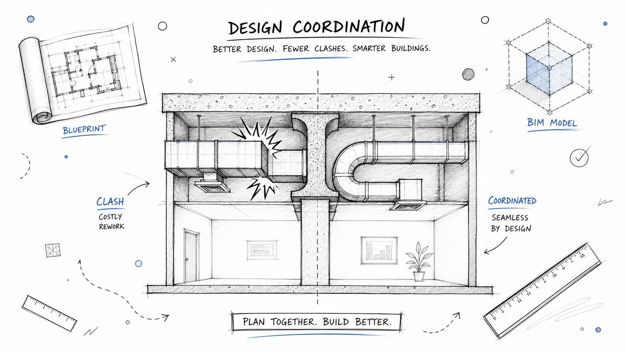
Adjacent-trade notes deserve the same attention as the primary component. Show or reference structural supports, mechanical clearances, electrical rough-ins, fire protection zones, waterproofing interfaces, and access requirements when they affect installation. Skipping those notes turns a coordination issue into a meeting, a field adjustment, or a change request.
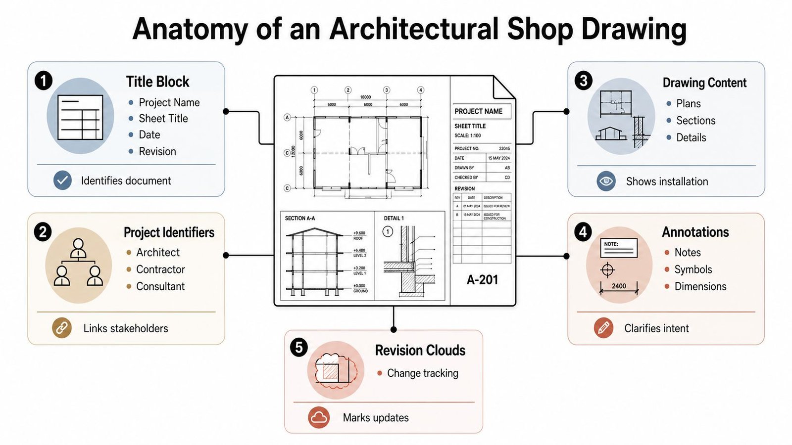
A sheet should earn every annotation
Use project-specific, accurately scaled information based on the applicable contract drawings. Construction coordination specifications can require trade-specific content to be added in a sequence that resolves conflicts before review, rather than relying on standard printed data. This project coordination specification illustrates why the source information and coordination order need to be controlled.
Code or jurisdiction stamps belong on the sheet when the project, authority having jurisdiction, or specification requires them. They shouldn't be added as decorative reassurance. The same principle applies to notes. If a note doesn't identify a requirement, clarify an interface, document a change, or direct installation, it may not belong on the sheet.
What the Architect Is and Is Not Reviewing
Architects often receive shop drawings with an implied question that the contract doesn't assign to them: “Can you confirm this can be built safely and exactly as proposed?” That isn't the normal design-professional review. Under AIA A201 §3.12.10, the architect's review is generally limited to conformance with the information given in the Contract Documents and the design concept expressed there.
The review protects the design intent. It doesn't convert the architect into the trade's detailer, manufacturer, site supervisor, or safety director.
Within the review envelope
A design professional can review whether the submittal generally aligns with the contract requirements and the design concept. Depending on the scope and discipline, that review may include:
- General layout: Confirm the component appears in the intended location, orientation, and relationship to the architectural design.
- Design-driving dimensions: Check dimensions that affect code-required clearances, visible alignments, openings, accessibility, proportions, and other design outcomes.
- Specification consistency: Verify the listed material, finish, product, and performance information against the applicable specification and approved submittals.
- Consultant interfaces: Review visible or significant alignment with structural, mechanical, electrical, plumbing, and fire protection information supplied in the project documents.
- Detail intent: Confirm that the proposed connections, profiles, joints, and transitions don't undermine the documented design concept.
These checks are meaningful, but they aren't a blanket certification of every dimension or fabrication decision.
Outside the review envelope
Means and methods belong to the contractor and responsible trade. That includes shoring sequences, prefabrication tolerances, temporary works, safety precautions, sequencing, rigging, installation procedures, and the detailed production process. A manufacturer's installation instructions may inform the package, but the architect's review of a listed product doesn't assume the manufacturer's installation responsibility.
The contractor also owns the internal coordination process. The architect may identify a design conflict or a deviation from the contract documents, but the contractor must organize the trade coordination needed to resolve it.
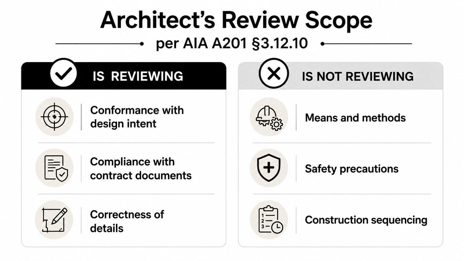
An “approved as noted” response doesn't transfer fabrication liability to the design team. The status, comments, and contractor's continuing responsibilities should remain clear in the submittal log.
A production lead should flag review comments that drift into construction methodology. “Align the visible mullion with the elevation grid” is a design-conformance comment. “Use this lifting sequence” is a means-and-methods direction unless the contract specifically assigns that role. Keeping the distinction visible protects the project team and makes review comments easier to act on.
Production Workflow That Stops RFIs Before They Start
A reliable production pod doesn't begin by opening a blank sheet. It begins by controlling the information that will feed the sheet. The following workflow works for internal teams and outsourced architectural shop drawing production because every stage has an owner, an input, and a decision checkpoint.
Intake and scope control
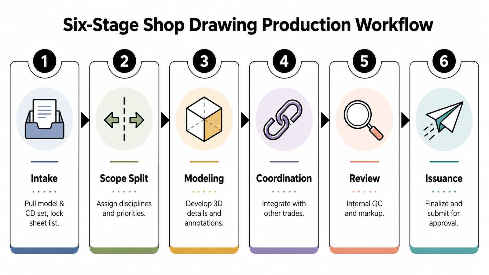
1. Intake. Pull the current Revit model, issued-for-construction set, specifications, approved submittals, addenda, relevant RFIs, and field dimensions. Lock the sheet list, project revision, title-block family, and transmittal requirements before drafting begins. The locked sheet list is the first RFI-prevention checkpoint because it prevents the pod from detailing against an incomplete or superseded package.
2. Scope split. Assign plan enlargements, elevations, sections, reflected ceiling details, partition types, finish schedules, and trade interfaces by package. Identify what the pod is producing, what the trade must provide, and what requires design-team direction. A scope split should make omissions visible before anyone starts drawing.
3. Model extraction. Pull live views from the coordinated model where appropriate. Set annotation phases, confirm view ranges, check detail levels, and audit view templates against the office standard. The view-template audit is the checkpoint that prevents inconsistent graphics, missing categories, and uncontrolled visibility settings from reaching the issue set.
A controlled template library should include the title block, sheet parameters, dimension style, keynote convention, detail component standards, and finish tag schedule. Those assets keep a rotating pod consistent across releases without forcing every new drafter to recreate office standards.
Draft, check, and issue
4. Sheet drafting. Generate callouts, finish tags, dimension strings, partition references, product notes, and required clearances. A drafter should sample a dimension chain before completing the package, checking that it closes back to a reliable datum and that the displayed dimensions agree with the model or verified field condition.
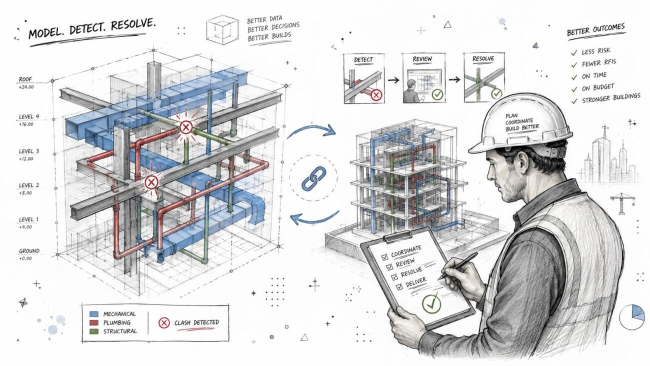
5. QA and coordination. Cross-check sheet references, revision triangles, keynote assignments, specification references, and material schedules. Run a clash pass against the federated model, then record open issues in a clash matrix with an owner and disposition. The matrix is more useful than a general statement that “coordination was completed” because it shows what was checked and what remains unresolved.
6. Issue. Package the drawings according to the contractor's submittal schedule. Include a transmittal that identifies the scope, current revision, preparer, contractor reviewer, and required response. The package should be complete enough that the reviewer doesn't need to reconstruct the source information from separate emails.
The workflow behind shop drawings for construction should be measurable through checkpoints, not just final-sheet appearance. A clean PDF can still contain the wrong revision, an uncoordinated penetration, or a missing approval reference.
2D, BIM, and Hybrid Shop Drawing Workflows Compared
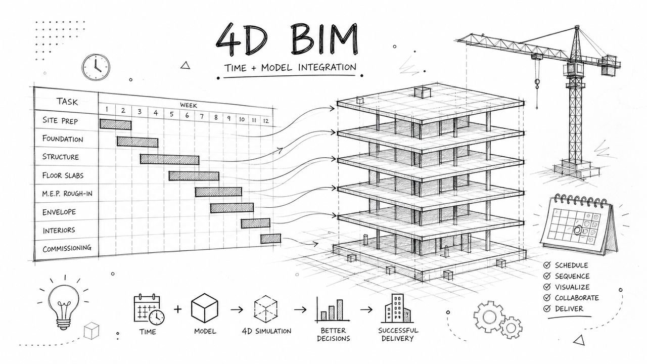
The right production method depends on what the project needs to coordinate, not on whether a team prefers CAD or BIM. A fast 2D workflow can be appropriate for a limited scope with stable information. A BIM-driven process earns its overhead when geometry, trade interfaces, and recurring revisions make model linkage valuable.
Three workable paths
2D-only CAD starts quickly from redlines, marked-up contract documents, or field information. It usually has the lowest software overhead and can be efficient for focused details, small packages, or late-stage corrections. The trade-off is that every coordination change must be manually propagated, and model relationships are difficult to verify.
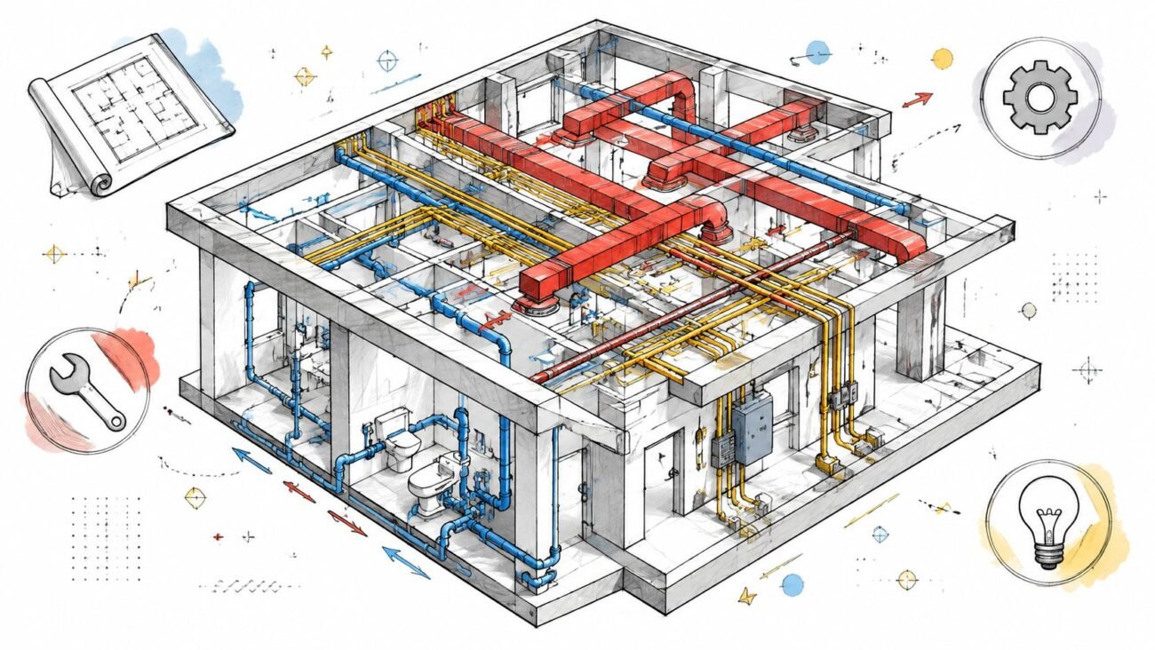
BIM-driven production generates sheets from a coordinated model. Revit can keep views, tags, schedules, and geometry connected, while Navisworks can support federated coordination and clash review. This approach is strong for complex fabrication interfaces and live revisions, but it depends on an LOD-matched model, reliable shared coordinates, accurate linked files, and disciplined view templates. Without those controls, teams produce a polished screenshot of an unreliable model.
Hybrid 2D plus BIM uses the model for heavy geometry and coordination, then uses CAD-style detailing or targeted 2D annotations where that is faster and clearer. Partition schedules, code callouts, finish tags, manufacturer notes, and certain enlarged details may be more efficient to complete in a controlled 2D layer or detail workflow than by forcing every piece of information into a model element.
Choose based on:
- Project complexity: More systems and interfaces generally justify stronger model coordination.
- Change exposure: Anticipated design changes increase the value of linked views and schedules.
- Issue format: Confirm whether the contractor needs a PDF set, native RVT, IFC, NWD, BCF, or another deliverable.
- Production maturity: A BIM workflow needs standards, permissions, templates, and QA. Software alone won't supply them.
| Criterion | 2D-Only | BIM-Driven | Hybrid 2D + BIM |
|---|---|---|---|
| Turnaround | Fastest to start for narrow scopes | Requires model preparation and setup | Balanced when scope is mixed |
| Fabrication accuracy | Depends heavily on manual checking and field data | Strong when the model is coordinated and verified | Strong for geometry, efficient for targeted annotations |
| Coordination effort | High manual cross-checking | Lower duplication, higher setup discipline | Moderate, with clear ownership between model and detail work |
| Software overhead | Lower | Higher | Moderate |
| Best fit | Fast-track interior revisions and limited packages | Large healthcare, aviation, and complex institutional work | Small tenant fit-outs and mixed-detail scopes |
The shop drawing example can help a buyer evaluate graphic completeness, but the production decision should also examine source-model quality, revision handling, and the team's QA evidence.
A Coordination Checklist You Can Hand to Your Team
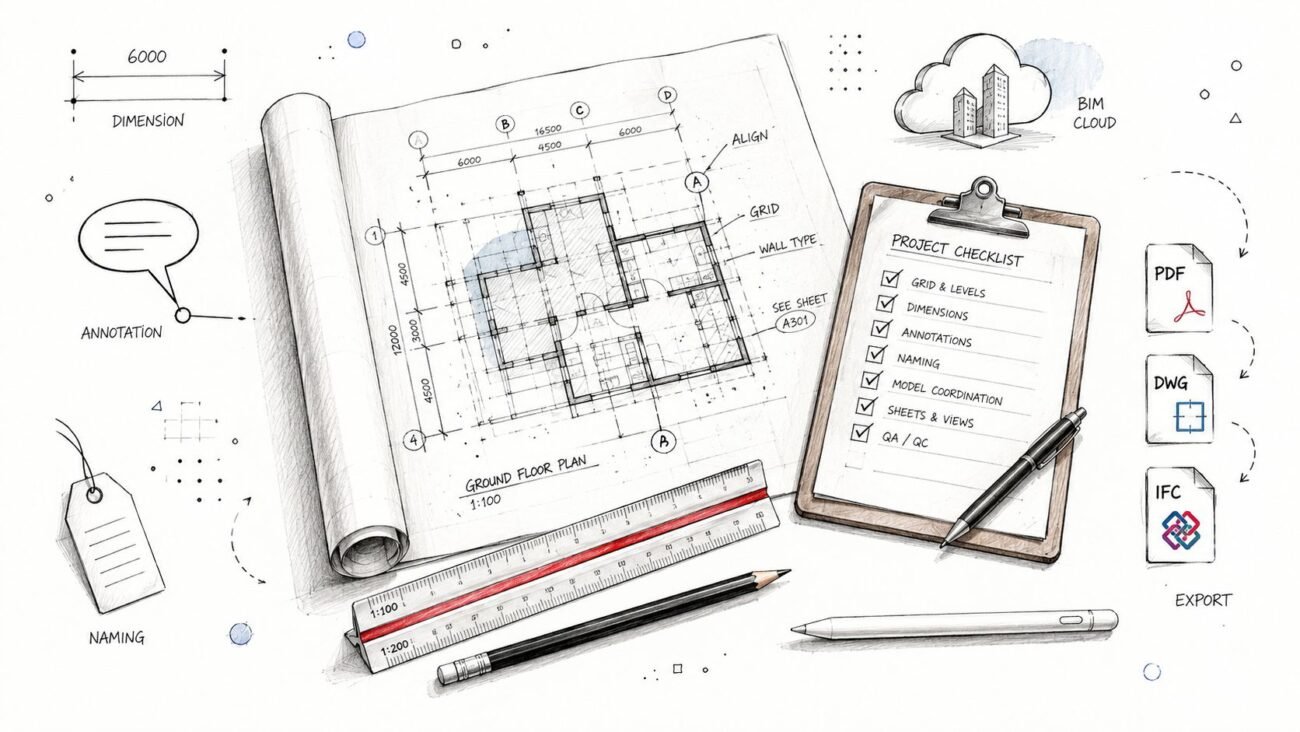
A checklist becomes useful when each item has an owner and a pass/fail condition. Give it to the project manager, BIM manager, drafter, contractor reviewer, and trade coordinator at kickoff. Keep the check focused on the information that controls fabrication, design-conformance review, and document traceability.
Pre-draw setup
Project manager
- Current source set: Confirm the model, construction-document issue, specifications, addenda, approved submittals, RFIs, and field information all identify the same controlling revision.
- Submittal scope: Name the trade package, required sheets, responsible preparer, contractor reviewer, and planned routing date.
- Contract boundary: Mark items reserved for architect review, contractor coordination, manufacturer responsibility, and field verification.
BIM manager or production lead
- Template package: Load the approved title block, sheet parameters, dimension style, keynote convention, detail standards, and finish tag schedule.
- Model health: Confirm linked models, shared coordinates, units, worksets, view templates, and required categories are usable for the scope.
- Sheet list: Lock the list before drafting. Pass means every required view and reference has an owner.
Model extraction and sheet drafting
Drafter
- View control: Confirm each view uses the correct phase, detail level, scale, crop, visibility settings, and template.
- Dimension chains: Check dimensions back to a known datum, show field-verified conditions where required, and identify tolerances or assumptions.
- Material references: Match product names, finishes, profiles, hardware, and specification sections to approved information.
- Interface coverage: Show structural supports, MEP clearances, electrical requirements, fire protection zones, access panels, waterproofing transitions, and other adjacent conditions that affect installation.
- Revision control: Add clouds, deltas, dates, and descriptions only for actual changes in the current issue.
QA and coordination
Internal reviewer
- Design conformance: Confirm general layout, visible alignment, design-driving dimensions, and specification consistency. Don't approve means and methods by accident.
- Reference integrity: Test every detail callout, keynote, sheet number, schedule reference, and product-data reference.
- Clash status: Compare the package with the federated model and record each identified conflict, assigned owner, resolution, and remaining action.
- Completeness: Verify that plans, elevations, sections, details, schedules, and material lists agree with one another.
Trade coordinator
- Clearance check: Confirm that adjacent systems can occupy the shown space without unrecorded field adjustments.
- Deviation log: Identify every departure from the contract documents and route it for written direction where required.
- Field condition: Confirm that dimensions marked “verify in field” have an assigned verification responsibility and aren't being treated as resolved.
Submittal routing
Contractor reviewer
- Submittal stamp: Confirm the package has received the contractor's internal review before design-team routing.
- Transmittal: Name the scope, revision, preparer, reviewer, requested response, and related submittal or RFI references.
- Release control: Prevent fabrication or installation from proceeding on a package whose contractual status doesn't authorize the next action.
Architect or design reviewer
- Review scope: Evaluate conformance with the contract documents and design concept, then separate design comments from contractor means-and-methods issues.
- Response clarity: Use comments that identify the sheet, detail, requirement, and required correction.
- Recordkeeping: Update the submittal log with the response status, comments, resubmittal requirement, and responsibility for incorporating changes.
A firm can turn this checklist into an SOP by adding its own naming rules, folder structure, review windows, and QA sign-off fields. If your team needs a neutral review of that framework, a consultation can help identify where an outsourced production pod would improve capacity without blurring responsibility.
BIM Heroes supports architectural shop drawing production through template-driven Revit and CAD workflows, with deliverables coordinated for architecture, engineering, and construction teams. If your team has a backlog, send the current model or drawing package for a practical scope review, then visit BIM Heroes to request a free consultation, LOD recommendation, and pricing within 24 hours.