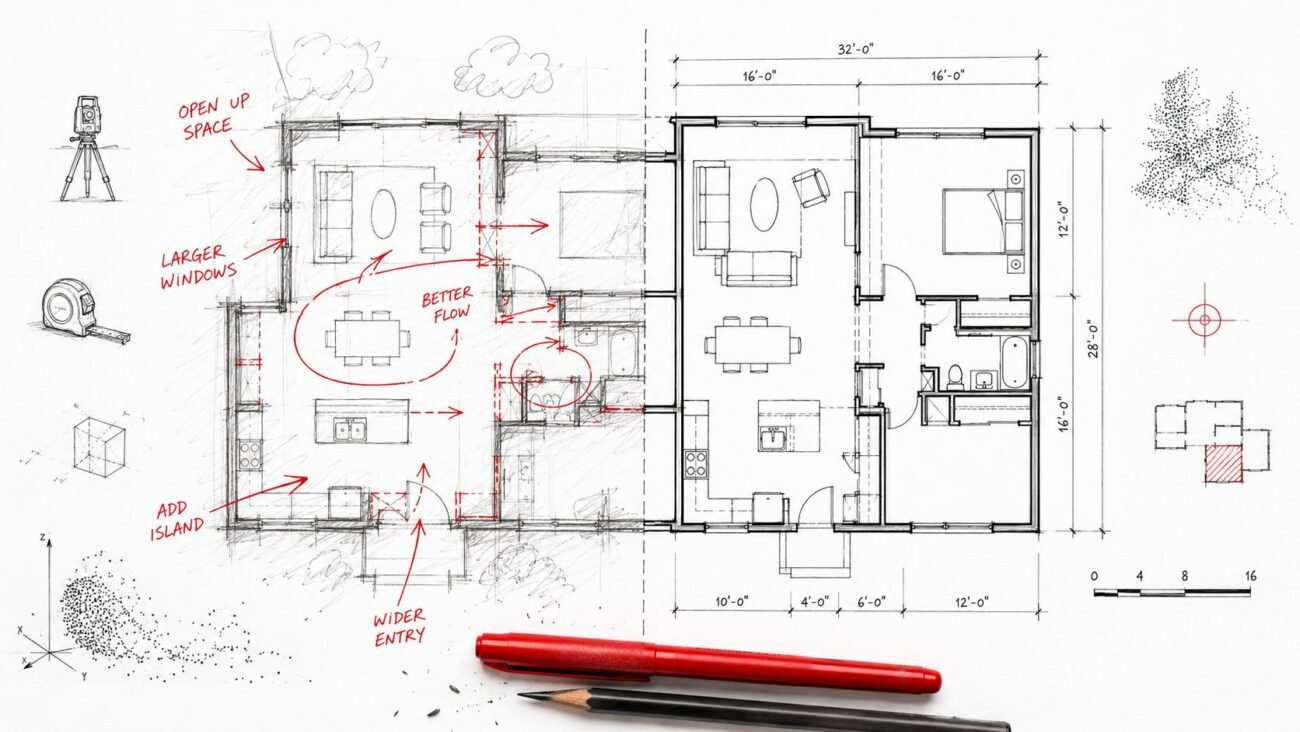
A contractor opens a ceiling in an occupied office tower and finds that the HVAC routing doesn't match the 1970s drawings. The slab edge is offset, a column sits somewhere the structural plan never showed, and the MEP redesign is now blocking the next trade. Nobody has time to measure the entire floor manually, and nobody wants to defend a model built from drawings that were already proven wrong.
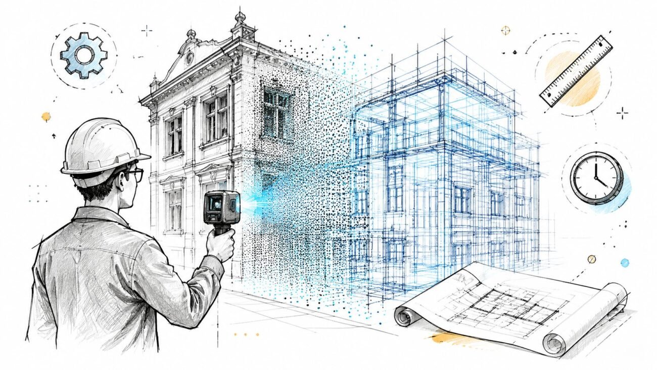
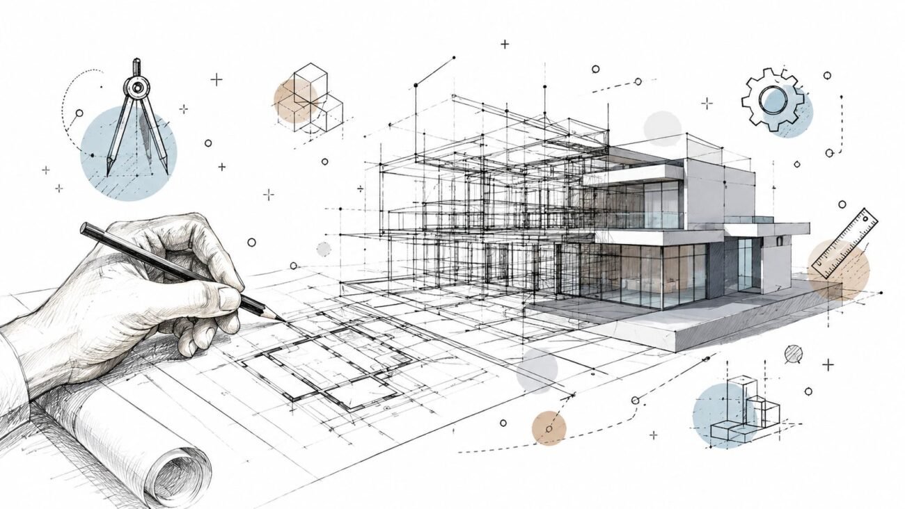
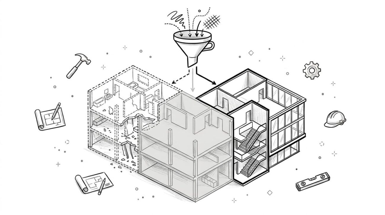
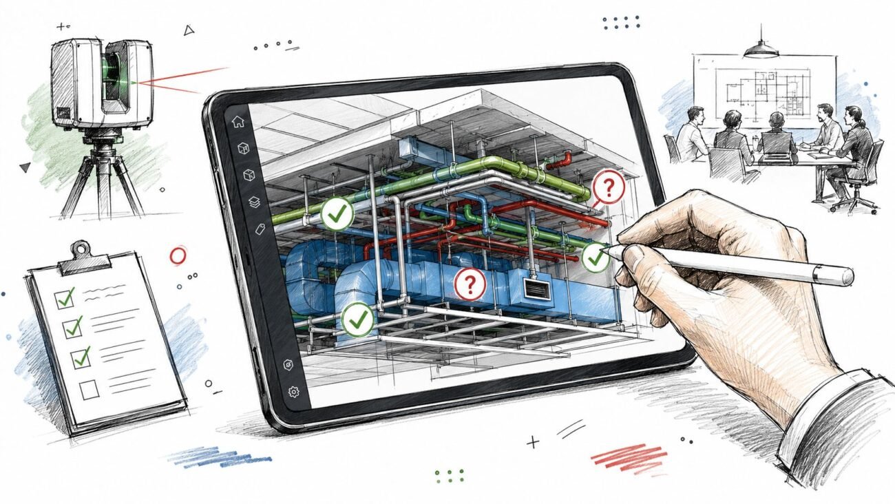
That's where laser scanning surveying earns its place. A properly planned scan captures the built condition as it exists, ties it to a defensible coordinate system, and gives the design and construction teams one verified source of geometry. The scan itself isn't the finished product, though. The value appears when the point cloud becomes a coordinated Revit model, an accurate as-built, a fabrication reference, or a deviation report that someone can use to make a decision.
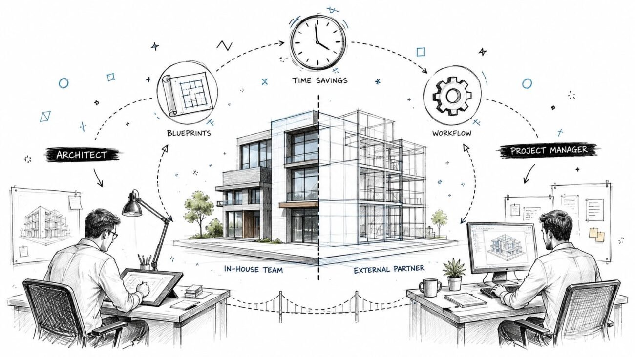
For firms that capture reality data but don't want to build every model internally, scan to BIM services can separate field capture from production without sacrificing naming standards, LOD discipline, or QA.
The Real Moment AEC Teams Decide to Scan
Laser scanning is not chosen because the technology looks impressive. It is chosen after an existing-condition assumption fails in a way that affects cost or schedule.
The office tower is a familiar example. The contractor has demolition underway, the ceiling grid is open, and the mechanical subcontractor discovers that supply ducts cross a beam where the coordination model shows clear space. The architectural backgrounds are close enough to look credible, but not close enough to route new services. A few isolated tape measurements won't resolve the full relationship between ductwork, structure, ceiling heights, shafts, and access zones.
At that point, the question changes from “Can we use the drawings?” to “What information can the project team trust?”
Field lesson: The scan becomes valuable when the cost of another assumption exceeds the cost of creating a verified existing-condition record.
Laser scanning surveying captures the geometry of the exposed and visible environment quickly, including relationships that are difficult to document with isolated measurements. It helps teams coordinate around actual slab edges, wall faces, equipment clearances, overhead services, and structural obstructions rather than relying on inherited linework.
The same decision appears in façade restoration, hospital renovation, industrial upgrades, tenant improvements, and phased construction. A project may have reliable drawings for one area and unreliable records for another. Scanning lets the team focus verification where uncertainty creates the greatest downstream risk.
The handoff still matters. A registered point cloud with unclear coordinates, missing metadata, or inconsistent naming can create another production problem instead of solving the first one. The practical workflow is described in this scan-to-BIM overview, but the underlying principle is simple: capture reality once, document the controls, and make the result usable by the people responsible for design, coordination, estimating, and construction.
What Laser Scanning Surveying Actually Is
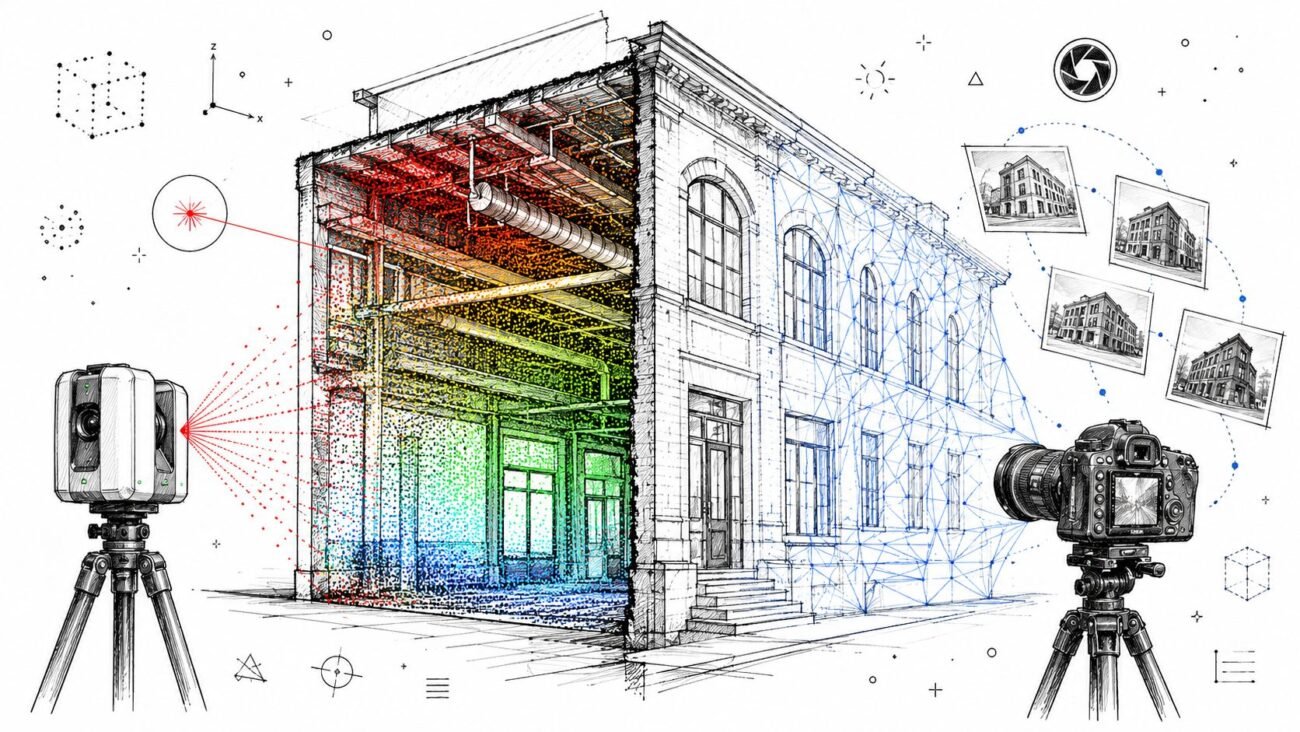
Laser scanning surveying uses a scanner to measure distances between the instrument and surrounding surfaces. Time-of-flight systems calculate distance from the return time of laser pulses, while phase-based systems use the change in the returned signal to measure distance. The scanner records each measurement in three-dimensional space, producing points defined by range and angle.
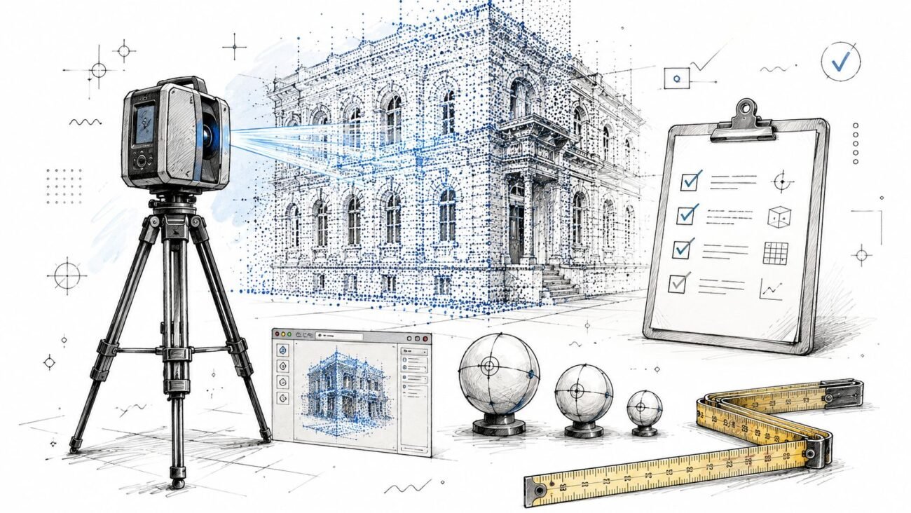
A terrestrial laser scanner, or TLS, collects these measurements from fixed stations. Each station sees only what is visible from its position, so a complete survey requires multiple locations with sufficient overlap. Registration software then aligns the individual scans into one point cloud.
The main capture platforms
Static TLS is the production choice when accuracy, density, and traceability matter most. Survey crews use it for detailed as-builts, mechanical rooms, façades, structural conditions, and areas where a model must support close coordination. Targets, survey control, and carefully planned station geometry help establish repeatable relationships between scans.
Mobile scanners and SLAM-based systems move through a space while collecting data. They're useful for long corridors, large floor plates, plant environments, and rapid interior coverage. Their advantage is field speed and mobility. Their limitation is that accumulated alignment error, weak geometry, movement, and environmental conditions can affect the final result, so the method must match the required tolerance.
The deliverable can take several forms:
- Registered point cloud: The aligned scan data, often provided for viewing, measurement, design reference, or further processing.
- Cleaned and segmented cloud: A processed dataset with noise reduced, sections organized, and unnecessary density controlled.
- Mesh or surface output: A triangulated representation used for visualization or certain analysis workflows.
- BIM model: A structured interpretation of the cloud, with walls, slabs, doors, equipment, piping, ducts, and other elements modeled to an agreed level of development.
Registration may use targets, survey control, cloud-to-cloud alignment, or a combination. The method matters because a visually convincing cloud can still be poorly positioned in project coordinates. A modeler needs to know not only what was captured, but also how the scans were aligned, what control was used, and which portions of the site were not visible.
How a Laser Scanning Survey Project Runs in Practice
A scan-to-BIM job is usually won or lost before the scanner is unpacked. The owner, survey crew, and modeling team must agree on the decision the data will support, the project coordinate system, control, coverage, file format, and modeling tolerance. A cloud for visual context does not need the same field discipline as one used for MEP coordination, deviation reporting, or construction verification.
The field sequence
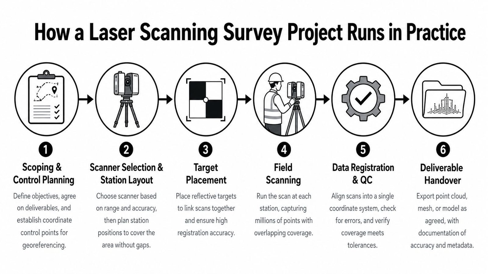
The production sequence typically runs as follows:
- Define scope and control. Confirm the rooms, elevations, façades, roof zones, or site limits, then establish the datums and control points needed for consistent project coordinates.
- Choose the capture method and stations. Range, line of sight, access, point density, and required tolerance determine whether static TLS, mobile scanning, or SLAM is suitable.
- Set targets and references. Targets connect stations and give registration software stable geometry. Poor distribution can weaken alignment even when each individual scan appears clean.
- Capture overlapping coverage. Every station must see the required surfaces and enough shared detail with adjacent stations to support registration. A fast setup that leaves isolated areas often creates modeling gaps later.
- Check the site before leaving. Review coverage, target visibility, registration indicators, and known control relationships. Missing a shaft, riser, or congested ceiling zone is cheaper to correct during the site visit than after demobilization.
- Process and hand over. Office staff filter noise, register scans, apply coordinate control, organize files, run QA, and export the agreed deliverables with exclusions and limitations clearly identified.
Where projects actually fail
The recurring problems are insufficient overlap, reflective surfaces, mislabeled targets, obstructed lines of sight, and rushed field checks. Glass, polished metal, standing water, dark finishes, and moving equipment can create gaps or noisy returns. A cloud may look complete in a viewer while still missing the connection a modeler needs to place a pipe, wall, or piece of equipment correctly.
That gap between field capture and modeling is where handoff quality matters. The survey team should identify inaccessible areas, occlusions, temporary obstructions, scan coverage limits, and coordinate assumptions. The modeling team needs those notes before tracing geometry or issuing a deviation report. Otherwise, a missing surface can be mistaken for a site condition, and a registration problem can become an apparent construction error.
Registration QA should examine more than a target-fit display. Reviewers should check drift through the scan network, overlap consistency, control relationships, gaps, and obvious blunders. Academic review work on TLS registration explains why target-based fit statistics can understate georeferencing error. A low residual does not by itself prove that the full scene is correctly aligned. The University of Southampton review on TLS registration quality provides useful background for evaluating the network rather than accepting one attractive statistic.
Where Laser Scanning Surveying Earns Its Place on AEC Projects
The right scanning method depends on the decision the data must support. A plant room model intended for MEP coordination needs dense, stable geometry around pipes, valves, equipment, and access clearances. A rapid interior sweep for early space planning may need broad coverage and usable proportions rather than exhaustive feature capture.
| Project Type | Recommended Method | Typical Accuracy Range | Primary Deliverable | Decision Value |
|---|---|---|---|---|
| Mechanical rooms and congested MEP areas | Static TLS with targets and control | Millimetre-level | BIM-ready point cloud and MEP model | Resolve routing, clearance, and clash risks |
| Façade documentation | Long-range static TLS with controlled stations | Millimetre-level at suitable working distances | Façade cloud, orthographic views, or model | Support condition review, repair planning, and design |
| Heritage interiors | Static TLS, often combined with imagery | High-detail, millimetre-level | Archival cloud, mesh, or detailed model | Preserve irregular geometry and support careful intervention |
| Large corridors and floor plates | Mobile or SLAM scanning | Project-dependent, generally less precise than controlled static TLS | Registered interior cloud | Build spatial context quickly |
| Early planning and visualization | Mobile, SLAM, or photogrammetric capture where suitable | Centimetre-level may be acceptable | Context model or visualization cloud | Test layouts and communicate existing conditions |
| Scan-to-BIM coordination | Static TLS for critical zones, supplemented by mobile capture | Set by the agreed modeling tolerance | Revit, IFC, or coordination model | Create a structured source for design and construction |
The comparison is not a ranking. It's a scope decision. Static TLS usually earns its cost where model geometry will drive fabrication, clash resolution, construction verification, or close as-built review. Mobile and SLAM capture can be the sensible option when the team needs fast coverage and the model only requires broad architectural geometry.
Photogrammetry can also be commercially appropriate. One comparative study found closer agreement between two lidar-derived clouds, with a mean absolute distance of 0.031 m and RMSE of 0.019 m, while a photogrammetric cloud using ground control showed 0.208 m mean absolute distance and 0.116 m RMSE. Those results support using TLS where millimetre-to-subcentimetre geometry matters, particularly for façades, MEP clashes, and existing-condition models. The comparative study in the ISPRS Archives provides the cited comparison.
Accuracy Standards That Govern Scan Deliverables
A scanner brochure describes instrument capability. It does not define the scan package a BIM team can accept.
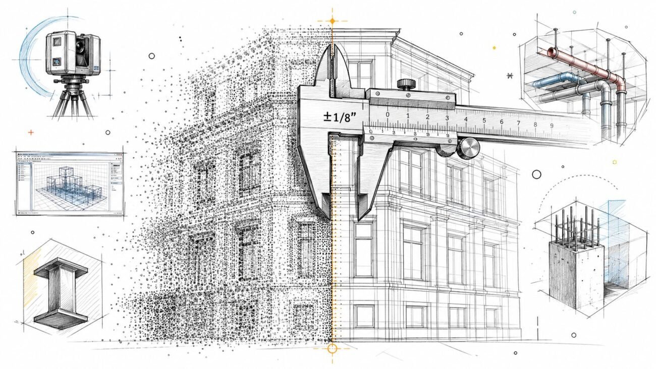
Field accuracy changes with distance, surface conditions, station geometry, survey control, registration, atmospheric effects, and the way modelers abstract the cloud. A Journal of Surveying Engineering evaluation under ISO 17123-9 reported uncertainty ranges of 2.7 to 3.9 mm at distances from 10 to 40 m, increasing to 7.7 mm at 50 m. The cited scan-to-BIM accuracy discussion includes those results. A usable specification therefore states where accuracy is tested and how acceptance is determined, rather than repeating a manufacturer's best-case figure.
Separate survey control from model fit
A registered cloud can satisfy its control requirement while the Revit model still fails the coordination task. The modeler may snap a wall to the wrong face, flatten a sloped slab, join ductwork poorly, or place an MEP element incorrectly. Those failures occur during interpretation and modeling, not necessarily during scanning.
Write the acceptance criteria before fieldwork. Define:
- Control accuracy: How the cloud relates to the project coordinate system.
- Relative accuracy: How nearby elements relate to one another.
- Registration quality: Whether scan-to-scan alignment remains stable across the network.
- Validation method: How the cloud or model will be checked against independent points or surfaces.
- Modeling tolerance: The deviation acceptable for the intended design or construction use.
The deliverable class should also be clear to both the scanning crew and the modeling team. A point-cloud standards guide for scan deliverables can help teams discuss expected control, density, and downstream use before data collection begins.
Public specifications show how much the requirement can change by purpose. Massport's laser scanning procedure requires construction-grade work tied to survey control and a 1/4-inch accuracy across the survey area. Massport's laser scanning standard offers a practical example of a project-specific threshold.
Caltrans specifies control points for point-cloud adjustment at 0.07 feet local network accuracy or better horizontally, with third-order vertical accuracy. Its Type A hard-surface topographic STLS surveys require validation accuracies of X,Y ≤ 0.03 feet and Z ≤ 0.02 feet, while Type B earthwork surveys allow X,Y,Z ≤ 0.10 feet. The Caltrans surveys manual demonstrates why tolerance must follow the deliverable's purpose.
For BIM production, the model specification belongs beside the survey specification. A point-cloud standards document from MALSCE defines deliverable classes by control accuracy, including 1/4-inch, 1/2-inch, and 3-inch point clouds with different network accuracy requirements. The buying question is simple: what acceptance test will the model pass?
The Production Cost Teams Miss After the Scan
The field crew may finish on site, yet production work is only starting. Capture is the visible line item. The less visible cost sits in storing, preparing, interpreting, and handing over data so another team can use it without rework.
Point clouds need a storage plan, file naming convention, access control, indexing method, and named owner. Large datasets can slow workstations and complicate cloud collaboration. Informal transfers also create duplicate versions. Staff then spend time finding the correct registration, checking coordinate systems, or confirming whether an area was processed.
A file can be valid and still be poorly prepared for production.
Treat the handoff as a production interface
A scanning company may provide E57, RCP, or LAS files. Modelers may still need to index, decimate, section, crop, and organize them for Revit or coordination work. The format is rarely the problem. The missing context is. A technically valid file may still be operationally unprepared for the next workflow.
The handoff should state:
- Coordinate information: Project datum, units, origin, rotation, and survey-control references.
- Registration records: Scan groups, target use, cloud-to-cloud operations, exclusions, and known limitations.
- Coverage notes: Scanned areas, inaccessible zones, occlusions, reflective-surface issues, and rescan recommendations.
- Version status: Approved cloud, superseded files, revision date, and responsible party.
- Modeling brief: Required elements, exclusions, target LOD, naming rules, and expected exports.
Semantic mapping adds another production task. A raw cloud contains geometry, not a searchable asset database. Someone must identify walls, slabs, pipes, ducts, equipment, hangers, insulation, and temporary site conditions. Those decisions affect whether the model supports coordination and asset management or remains a difficult-to-search visual reference.
Repeated scanning adds a lifecycle burden. Teams must manage storage, large datasets, atmospheric and meteorological effects, sensor instability, and time-series alignment. The MarketsandMarkets overview of terrestrial laser scanning also reflects the field's emphasis on integration, semantic mapping, and long-term monitoring alongside acquisition. The practical test is simple: can the modeling team identify the approved data, understand its limits, and begin production without reopening the field workflow?
Why the Modeling Step Decides Whether the Scan Was Worth It
A field crew can deliver clean, well-registered data while the project still loses value. The point cloud records existing geometry, but it does not become a coordinated BIM asset on its own.
Modelers decide how that evidence supports design, construction, and handover. They clean noise, separate disciplines, identify modelable elements, assign LOD, resolve ambiguous geometry, and create relationships that downstream users can query. They must also distinguish permanent construction from temporary obstructions, assess hidden continuations cautiously, and record assumptions instead of presenting uncertainty as precise geometry.
Model detail must match the decision it supports
A visually polished model can still fail coordination if it omits the information that affects decisions. Walls may be present while openings, offsets, shafts, equipment clearances, or MEP connections are missing. Designers and contractors then return to the cloud whenever a question matters.
Over-modeling creates a different production problem. Reproducing every bracket, fitting, or surface irregularity consumes time without improving a coordination-level deliverable. LOD should follow the model's intended use, not a blanket promise to represent every element at maximum detail.
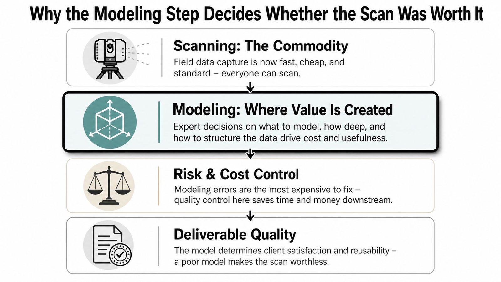
The handoff between scanning and modeling determines whether these choices are controlled. The production team needs usable cloud views and sections, discipline priorities, approved templates, naming rules, shared coordinates, and a defined method for checking modeled geometry against the scan. Deviation review should expose exceptions, not only confirm that a model exists. Required coordination files may include RVT, IFC, DWG, NWD, or BCF.
A practical review asks three questions: Can the model answer the project's coordination questions? Are deviations recorded in a way the design team can act on? Can another team continue production without interpreting undocumented assumptions?
In-house teams often struggle when scan-to-BIM work arrives in bursts. A designer may know the building but lack uninterrupted modeling time, while a BIM manager understands the standards but is occupied with active project issues. A specialized production pod can maintain templates, review gates, and handoff rules across changing workloads.
For tool selection, point-cloud software guidance belongs beside the production plan. BIM Heroes processes scanner data from Leica, FARO, Matterport, NavVis, Trimble, and DotProduct, with a stated workflow supporting Revit, ReCap, Leica Cyclone, FARO Scene, and Navisworks. Its scan-to-BIM service describes verification to ±1/8 inch with a deviation report on every model, deliverables from LOD 200 to LOD 350, and RVT, IFC, DWG, NWD, and BCF outputs. Those specifications have value only when the provider ties them to a written scope, review method, and acceptance process.
A Practical Checklist Before You Commission or Outsource a Scan
A scan request that says “capture the existing conditions and provide a BIM model” isn't a usable scope. It leaves the survey crew, modeler, and client to make different assumptions about accuracy, coverage, detail, and file ownership.
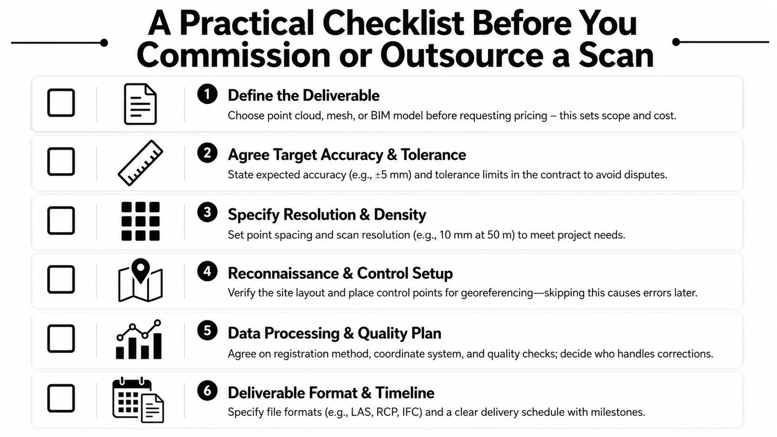
Set the decisions below before pricing.
- Define the deliverable. Choose point cloud, mesh, BIM model, orthographic output, or a combination. A point-cloud-only brief shouldn't be priced like a coordinated Revit model.
- Agree on accuracy and tolerance. State the required survey accuracy, relative tolerance, validation method, and acceptable deviations in writing. Don't rely on a scanner's headline specification.
- Confirm coordinates and control. Identify the project datum, units, shared coordinates, survey benchmarks, control points, and required georeferencing.
- Specify the modeling target. Name the LOD, disciplines, element categories, exclusions, family requirements, and whether the model supports design, coordination, fabrication, or as-built documentation.
- Define processing and QA. Confirm registration method, cloud density, decimation, noise handling, deviation reporting, review stages, and responsibility for corrections.
- Lock down formats and ownership. Confirm RCP, E57, LAS, RVT, IFC, DWG, NWD, or BCF requirements, plus storage location, revision control, intellectual property, and handoff ownership.
The commercial test is straightforward. If the project needs a coordination model, price the modeling, QA, deviation documentation, and revisions as part of the scan-to-BIM workflow rather than treating them as optional cleanup. If the project only needs broad spatial context, don't buy a level of capture or modeling detail the users won't read.
A pre-engagement review can expose those mismatches early. BIM Heroes offers a free LOD recommendation and pricing within 24 hours, with a stated 5 to 7 day turnaround and rush availability, plus compatibility with BIM 360, ACC, Procore, and Bluebeam.
BIM Heroes can take point-cloud data from your scanning workflow and turn it into structured Revit and coordination deliverables with defined LOD, deviation reporting, and production QA. Send us your scan data or book a free consultation through BIM Heroes to review the project scope, identify the right modeling tolerance, and receive a practical LOD recommendation with pricing within 24 hours.