Meta description: Fix sloped roof Revit section problems before they hit CDs. Learn when to use Revit roof by footprint vs extrusion, how to control view range, and how to keep pitched roof Revit construction documents clean and predictable.
Category: BIM Technology & Workflows
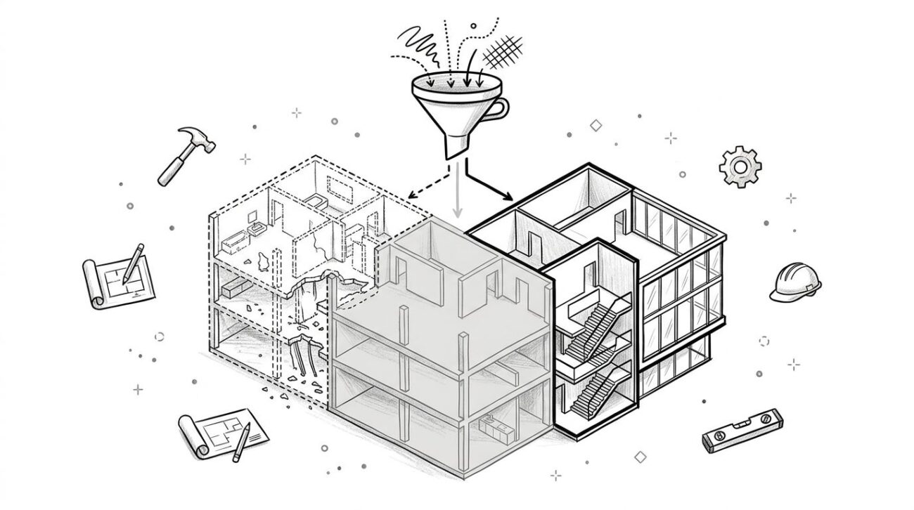
You've modeled the roof. The plan looks fine. Then you open a section and the assembly cuts as a strange diagonal slash, or the roof disappears entirely in one view while showing in another.
That failure is familiar on houses with sloped roofs, especially when the model was built quickly and the section setup came later. In most cases, the geometry isn't the problem. The issue is the combination of roof creation method, level constraints, and view settings.
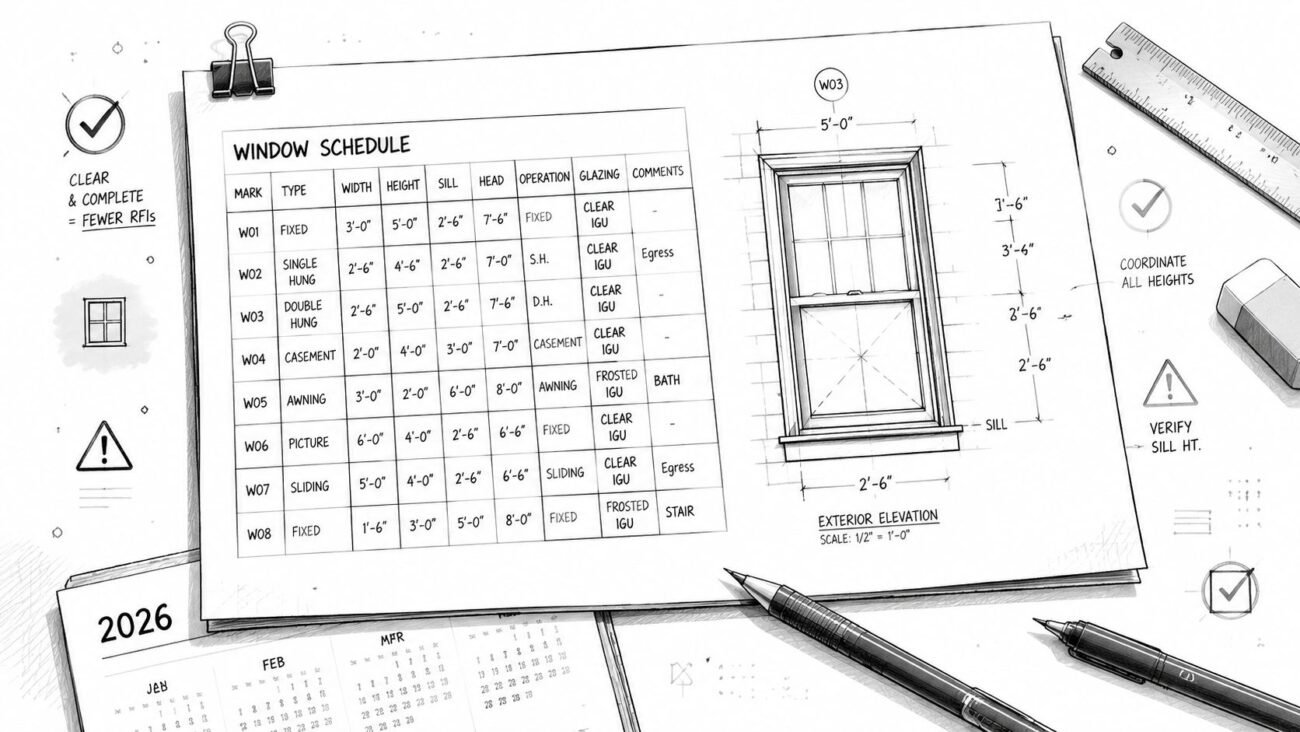
A sloped roof Revit problem usually traces back to a small setup mistake that keeps propagating into documentation. If you catch it early, the fix is simple. If you catch it during CDs, it turns into view-by-view cleanup, inconsistent details, and avoidable RFIs.
The clean way through is production discipline. Pick the right roof tool, sketch the roof with intent, and lock down section templates before the team starts duplicating views for permit sheets.
Introduction
You know the moment. The roof is in the model, the exterior elevation looks acceptable, and then the section cuts go sideways. One section shows a diagonal cut through the roof build-up. Another section won't show the ridge at all. In a third view, the roof and wall don't even meet.
That's usually not a broken model. It's a configuration problem inside Revit.
For houses with sloped roofs, section behavior changes fast when the cut intersects a sloped surface at different heights, when the Revit view range roof settings clip the element, or when the roof's base constraint doesn't line up with the view's associated level. Those are predictable production issues, and they're fixable.
This post stays focused on what prevents rework. It covers the two roof modeling methods, the setup choices that make section views stable, and the QA checks that keep pitched roof Revit construction documents consistent across the sheet set.
Why Sloped Roofs Break Revit Section Views
Sloped roofs are common in residential work for good reason. Pitch improves drainage, which is a basic durability requirement in housing, and roof slope is commonly expressed as rise over run. A 4:12 slope means the roof rises 4 inches for every 12 inches horizontally, as noted in this overview of why sloped roofs matter in residential construction. That same geometry that helps real buildings shed water is what makes Revit sections less forgiving.
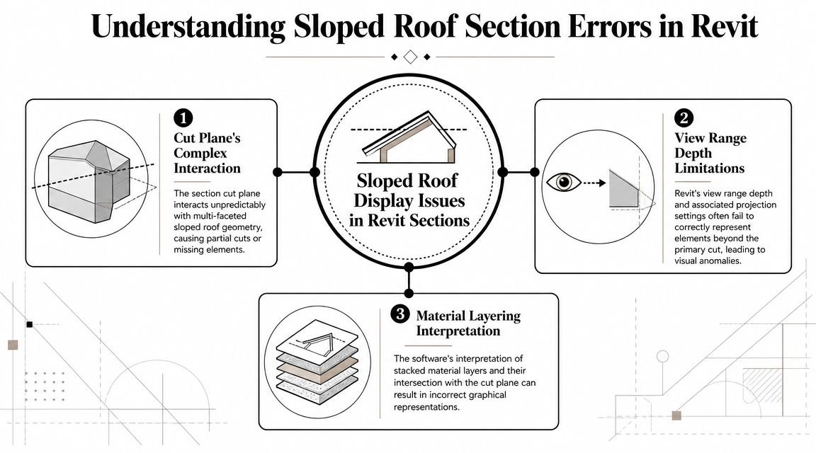
The cut plane doesn't hit a sloped roof consistently
A horizontal cut through a sloped assembly won't read the same at every section location. Move the section head a little, and the cut intersects a different elevation of the roof. That's why one section looks clean and the next looks wrong, even when both are technically “correct” from Revit's point of view.
View range clips more often than teams expect
The second issue is visibility depth. If the top of the section view or related range settings stop below the ridge, Revit may clip the roof or show only part of it. Staff often treat this as a graphics problem when it's really a setup problem.
Base constraints and associated levels have to agree
The third issue is level logic. If the roof is hosted or constrained to one level and the section is associated to another level with different extents, the view can read the element unpredictably. That gets worse after copy-monitor changes, late level adjustments, or imported CAD background cleanup.
Practical rule: If a sloped roof displays differently in similar sections, check constraints and view settings before you touch the geometry.
A lot of teams lose time “fixing” edges, joins, or materials when the underlying problem is view control. This is the same pattern behind many hidden geometry errors that break Revit models. These aren't Revit limitations. They're configuration issues, and they're all fixable.
Roof by Footprint vs Roof by Extrusion
If the roof form is standard residential geometry, start with Revit roof by footprint. It gives you the most predictable result for plans, sections, wall attachment, and downstream edits.
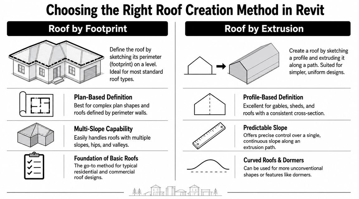
When footprint is the right call
Use Roof by Footprint for:
- Gable roofs where opposing edges define the slope cleanly.
- Hip roofs where multiple sloping edges need to resolve automatically.
- Shed roofs where one directional slope drives the form.
- Multi-ridge residential roofs built from separate footprint sketches joined deliberately.
This method works best because the sketch lives in plan, which is where most residential roof coordination starts. It also behaves better when you attach wall tops to the underside of the roof.
When extrusion earns its place
Use Roof by Extrusion when the form is profile-driven, not perimeter-driven. That usually means:
- Curved or arched roof profiles
- Special dormer forms
- Single-profile shapes where the section profile matters more than the plan outline
Extrusion is useful, but it creates avoidable section problems when the extrusion direction doesn't align well with the section cut. Teams use it too early because the profile is easy to draw in elevation. Then the roof behaves poorly in views that weren't part of that original setup.
Don't choose the fastest sketching method. Choose the method that will survive section cuts, wall joins, and permit revisions.
Simple decision guide
| Roof condition | Recommended method | Why it's safer in production |
|---|---|---|
| Standard pitched roof | Roof by Footprint | Better plan control and cleaner wall attachment |
| Curved or arched profile | Roof by Extrusion | Profile-based shape is easier to define accurately |
| Complex multi-ridge plan | Multiple Footprints with Join Geometry | More stable than forcing one oversized sketch |
| Custom drainage direction | Footprint with slope arrows | Gives controlled runoff behavior without odd sketch logic |
For most houses with sloped roofs, Footprint is the workhorse. Extrusion is a specialty tool. Treat it that way and your sections will stay far more predictable.
Setting Up the Roof Sketch Correctly
Most roof problems start in the sketch. Not in the section. Not on the sheet. In the sketch.
If you want stable pitched roof Revit construction documents, the footprint has to be built like a constructible roof, not like a diagram.
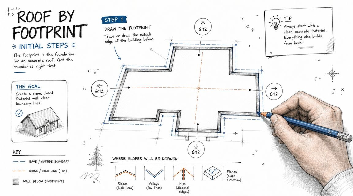
Get slope-defining edges right first
In Roof by Footprint, each boundary line can define slope or stay non-slope-defining. That single checkbox controls where ridges and valleys form.
Common mistakes:
- Too many slope-defining edges create unwanted hips or distorted ridges.
- Missing slope-defining edges flatten part of the roof unexpectedly.
- Wrong edge assignment shifts the ridge away from the intended structural centerline.
For a basic gable, only the two opposing eave edges should typically define slope. For a shed, usually one direction drives the slope and the remaining edges stay non-slope-defining.
Use rise over run when documenting construction intent
Revit lets you think in degrees, but residential roof work is commonly coordinated in rise over run. That aligns better with field communication and documentation standards for sloped residential roofs. Keep degrees for design studies if you need them. For CDs, rise:run is usually the cleaner choice.
Don't draw the footprint at the fascia
The footprint boundary should represent the structural bearing line or top plate logic, not the fascia edge. The overhang belongs in the overhang setting.
That matters because teams often trace the outside face of walls or the fascia line from CAD underlays. Then the roof sits too far out, wall attachments fail, and the eave detail no longer matches the model intent.
Field-minded note: The sketch controls the roof's logic. The overhang controls the expression. Don't mix them.
Flat areas need slope zero, not a floor
If part of the roof should remain flat within a sloped assembly, use slope = 0 on the relevant boundary behavior instead of modeling a separate floor as a workaround. Floors may look acceptable in one section, but they create documentation confusion fast. They also break consistency in schedules, roof tags, and assembly control.
Use slope arrows when drainage doesn't follow the perimeter
Some roofs don't resolve correctly by boundary lines alone. Crickets, tapered transitions, and offset drainage paths are good examples. In those cases, slope arrows are the cleaner method because they let you direct runoff deliberately without overcomplicating the sketch.
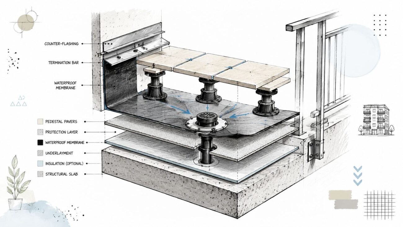
That matters even conceptually. Low-slope roofs are generally described as having more than 0/12 but less than 2/12, with an angle below about 14.5°, and because water sheds more slowly, those assemblies rely heavily on membrane detailing and explicit drainage design, as summarized in this discussion of low-sloped roofing system practice. In Revit terms, if the drainage path matters, model it intentionally.
Join multiple roof sketches carefully
For complex houses with sloped roofs, a single sketch often becomes unstable. It's usually better to create multiple footprint roofs and join them.
Use this sequence:
- Model the primary roof masses first so the main ridges are locked.
- Add secondary roof areas such as wings, garage roofs, or porch roofs as separate elements.
- Apply Join Geometry after each element is behaving correctly on its own.
- Check the join in section and 3D, not only in plan.
If Join Geometry produces a gap, don't force it with linework. First verify that both roofs have compatible extents, matching reference intent, and clean sketch boundaries. Gaps often come from a tiny sketch mismatch or inconsistent base constraints, not from the join tool itself.
Fixing Common Section View Display Problems
Once the roof is modeled, section cleanup should be systematic. If your team is correcting each view manually, the project has already drifted out of production control.
Problem 1, the roof shows as a diagonal slash
Cause: The cut plane is intersecting the sloped roof surface directly.
Fix: Set the cut plane below the lowest soffit so the roof displays in projection instead of as a partial cut through the assembly. In residential sections, this often gives a much cleaner read.
Problem 2, the roof disappears
Cause: The section's top extent is clipping the ridge or upper roof build-up.
Fix: Raise the top of the view range so the entire roof geometry sits within the visible range. If the roof appears in one section and not another, compare those extents before changing anything else.
Problem 3, the same roof looks different in different sections
Cause: Inconsistent section settings, mismatched associated levels, or both.
Fix: Use a dedicated template for roof sections and audit the roof base constraint against the project levels. If one section was duplicated from a working parent and another was built ad hoc, that inconsistency usually shows up fast.
A lot of teams also misuse join and cleanup tools in this phase. If you're repairing edges, make sure you understand what Cut Geometry in Revit actually changes and what it doesn't. It won't solve a bad view range.
Problem 4, there's a gap at the wall-to-roof junction
Cause: The wall top is unconnected.
Fix: Use Attach Top/Base to attach the wall to the roof underside. Then verify the wall type and roof build-up are displaying at the correct detail level.
A roof-to-wall gap in section usually isn't a detail problem first. It's a host relationship problem.
Fast audit checklist
Before editing geometry, check these in order:
- Associated level for the section
- Roof base constraint and offset
- View range top relative to ridge
- Cut plane relative to soffit
- Wall attachment at roof intersections
This sequence is faster than chasing graphics overrides view by view.
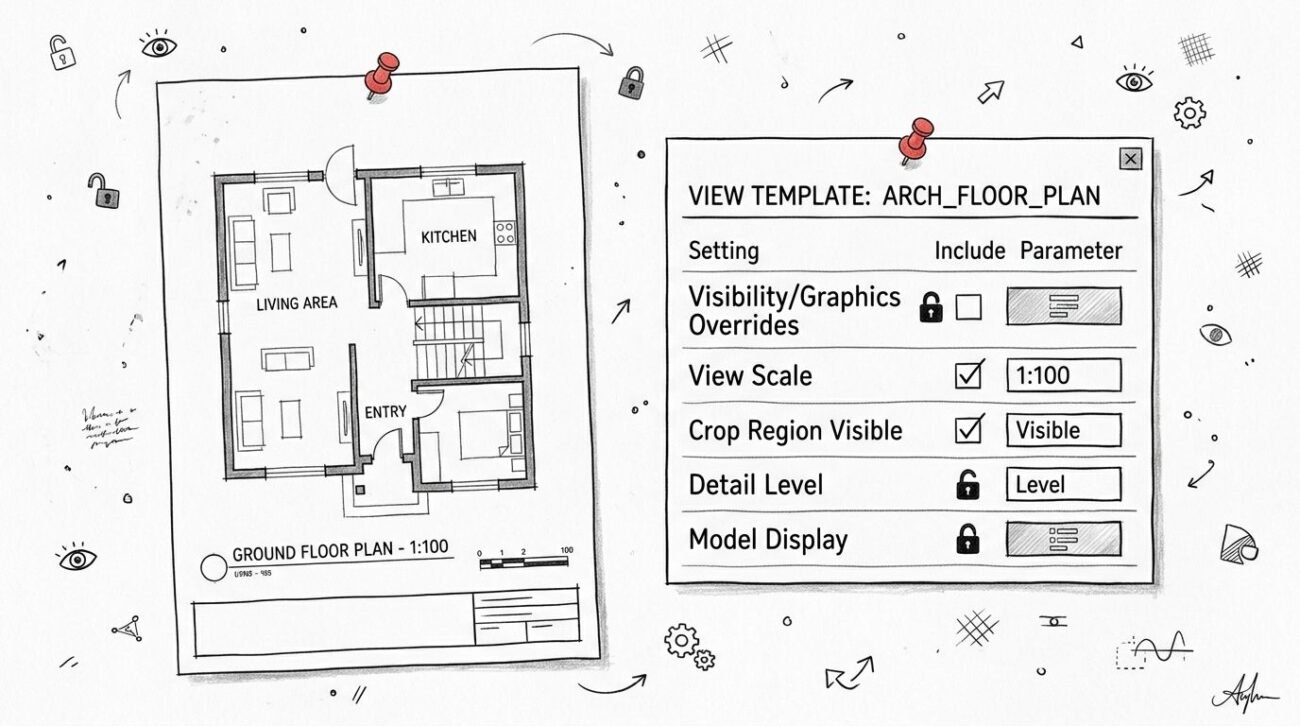
Creating a View Template for Sloped Roofs
Most sloped roof display issues spread because nobody set a dedicated section template early. One user fixes one section locally. Another duplicates a different section with different settings. By permit time, the set contains five versions of what should have been one standard.
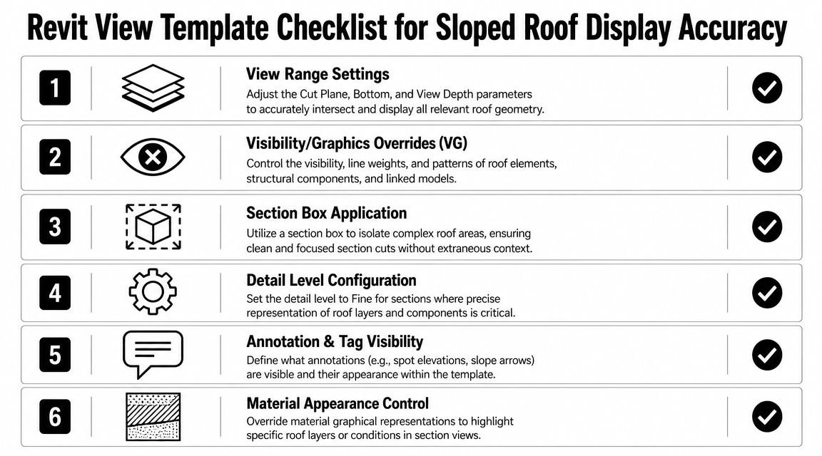
What the template should control
Build one roof-section template with these settings:
- Top extent above ridge: Set the top at least 2 feet above the ridge.
- Cut plane below soffit: Keep it below the lowest soffit so roof assemblies usually show in projection.
- Discipline: Set to Architectural.
- Detail level: Use Fine for CDs and Medium during design if that matches office standards.
- Roof graphics: Override roof category graphics at the template level, not per view.
- Parts visibility: Set to Show Original unless the team is intentionally using Parts.
Why template discipline matters
The template isn't just for appearance. It protects consistency. It keeps every section using the same logic for roof visibility, cut behavior, and assembly representation.
If your office doesn't already standardize this, build it into startup. A dedicated set of Revit view templates for production control is one of the simplest ways to stop sloped roof issues from multiplying across the model.
Handling Complex Roof Conditions
Some roof conditions need a different modeling sequence because the standard workflow won't stay stable.
Dormers need the right order
Model the dormer roof first. Join it to the main roof. Then cut the opening in the main roof sketch.
If you cut the opening first, then build the dormer around it, you'll usually create cleanup work in sections and details. Dormer sections also don't always read clearly in one cut. It's often better to use a primary building section plus a callout or a separate targeted section through the dormer.
Varying slopes won't center the ridge
When adjacent roof planes use different slopes, the ridge won't land in the middle. That's correct behavior. Don't “fix” it to look symmetrical if the geometry says otherwise.
Document it clearly in section and roof notes so nobody assumes the offset is a modeling error.
Parapets at sloped roofs must stay separate
Model the parapet as its own wall with its own top constraint. Don't try to fold it into the roof logic. You need independent control of the wall and the sloped roof for clean sections and edge detailing.
This also matters because, in code and drafting practice, a surface with a slope of less than 60° from horizontal is treated as a roof, while 60° or more is treated as a wall, as outlined in this energy code reference on roof and wall classification. In production terms, steep geometry can shift categories and detailing assumptions faster than teams expect.
Multi-layer assemblies need aligned constraints
If the roof assembly is complex, keep all layers tied to the same base constraint logic. Misaligned layers create eave conflicts, parapet cleanup issues, and misleading sections at enlarged details.
Complex roof conditions don't usually fail because the form is impossible. They fail because the modeling sequence was improvised.
When to Bring In Production Support
A common failure point looks like this. The roof model is in place, sections are on sheets, and one change to a slope line or attachment breaks five views at once. At that stage, the problem is no longer just roof geometry. It is a production control issue affecting view templates, annotations, and sheet coordination.
Bring in production support when the team is spending repeated hours on the same roof behavior without getting a stable result. I use a simple threshold. If the model still needs manual cleanup every time someone regenerates a section, edits a roof sketch, or updates wall attachments, the workflow is not under control.
The risk is rework.
By CDs, a sloped roof problem rarely stays isolated to one view. It spreads into enlarged sections, callouts, soffit details, wall intersections, and sheet notes. That is the point where outside production help saves time because the primary task is QA. Someone needs to check category visibility, cut plane behavior, join conditions, attachment logic, and template consistency across the set.
BIM Heroes architectural production support works with US architecture firms on this kind of Revit cleanup, including complex roof geometry, section view remediation, and documentation support when a permit set is being delayed by model behavior.
Conclusion
Most sloped roof section problems in Revit come from setup, not from the roof itself. If the base constraints are clean, the slope definition is deliberate, the wall tops are attached, and the section template is controlled, the model usually behaves.
That's the key production lesson. Don't wait for the section views to fail before you standardize the roof workflow. On houses with sloped roofs, early discipline saves far more time than late cleanup.
If a roof is already disrupting your CD set, treat it as a modeling standards issue first. That approach is faster, more repeatable, and far easier to scale across a team.
If your team is stuck on a sloped roof Revit problem, BIM Heroes can help with Revit production support, roof geometry cleanup, and section view remediation for US architecture firms. Send a project brief if a roof issue is slowing down your permit set.