Meta title: Panelized Wall Systems and BIM: Manufacturing-Ready Models
Meta description: Why a design-intent BIM model isn't the same as a manufacturing-ready one and what panel manufacturers need to fabricate.
A familiar failure point shows up right after the design team says the model is done.
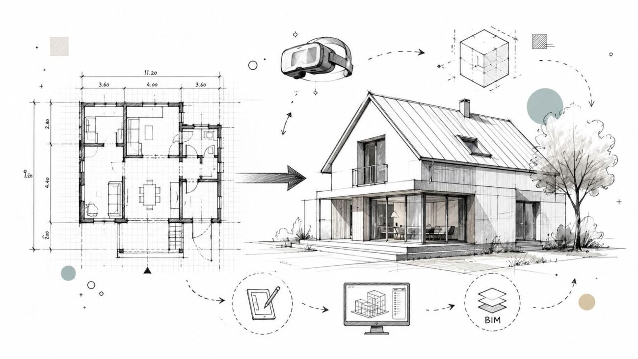
The architect has a coordinated Revit file. Openings look right. Wall types are assigned. Sheets are issued. Then the panel manufacturer reviews the package and sends it back with questions about panel breaks, bearing assumptions, opening control dimensions, connection geometry, and tolerances that were never modeled clearly enough to fabricate from. The team thought it had reached the finish line. In reality, it had reached a handoff that wasn't ready.
That gap matters more on panelized wall systems than many teams expect. These systems move framing work offsite, often with structural framing and sometimes sheathing, insulation, or other components integrated before delivery. The speed advantage is real. The global panelized building systems market was valued at USD 14.5 billion in 2023 and is projected to reach USD 24.9 billion by 2033 at a 7.9% CAGR, according to Data Insights Market's panelized building systems market report. But offsite speed only works when upstream documentation is precise enough for production.
A design-intent BIM model and a manufacturing-ready BIM model are not the same deliverable. Treating them as interchangeable is what creates RFIs, stalled submittals, and schedule loss before fabrication even starts.
Design-Intent Models vs. Manufacturing-Ready Models
A good design-intent model isn't a bad model. It's built for a different job.
Most design teams model to support planning, coordination, permit review, client review, and drawing production. That's appropriate. In that environment, a wall can be "correct" if it has the right location, type, fire rating, thickness, and general opening layout. That level of information supports design decisions and code review. It doesn't automatically support fabrication.
A manufacturing-ready BIM model has to answer a narrower, tougher question. Can a manufacturer use this model and its linked documentation to break the building into producible wall panels, create panel fabrication drawings, and issue the work to the shop without a long trail of clarification requests?
What changes between the two
The easiest way to explain the difference is by purpose.
| Model type | Primary use | Typical strength | Common gap |
|---|---|---|---|
| Design-intent model | Design coordination, permit sets, client review | Spatial coordination and assembly intent | Doesn't define fabrication logic |
| Manufacturing-ready model | Shop production, panel segmentation, fabrication review | Exact production inputs | Requires earlier decisions and tighter control |
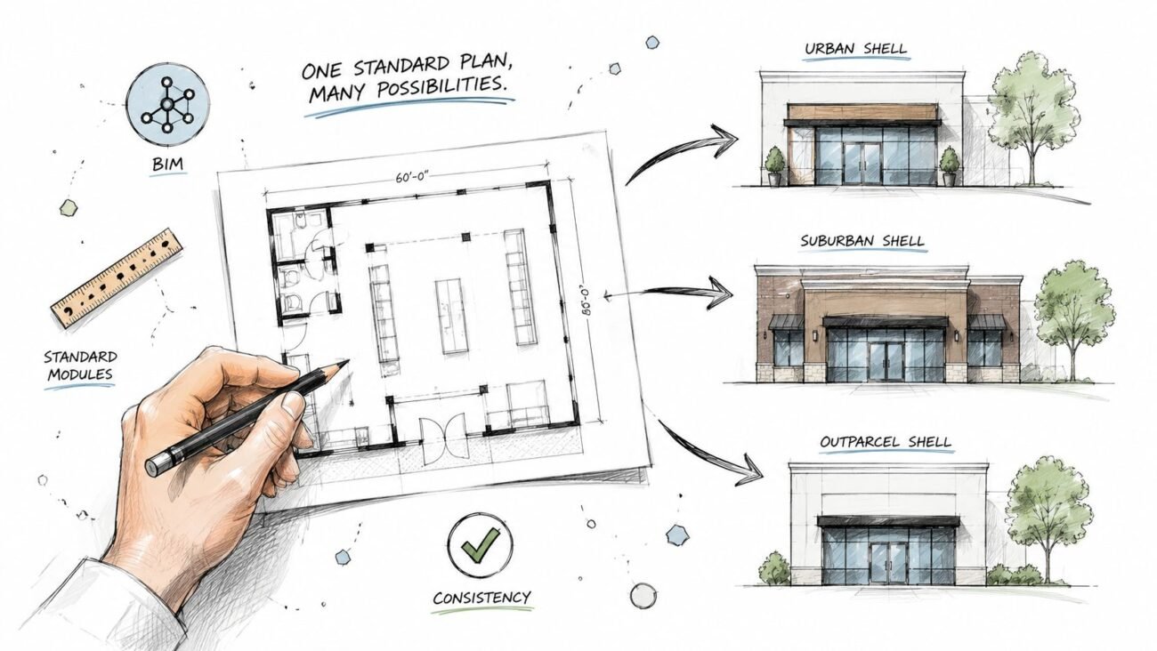
In practice, the design-intent model says, "this is the wall assembly we want."
The manufacturing-ready model says, "this exact panel starts here, ends here, carries this opening at this confirmed location, receives this connection, and fits within this tolerance stack."
Field lesson: A model can be excellent for permitting and still be unusable for fabrication.
Why teams confuse them
Revit, Archicad, and other BIM tools make geometry look finished long before the production logic is settled. That's where many teams get trapped. A wall looks complete in 3D, so everyone assumes the panel package is close. It often isn't.
The confusion gets worse when the project team delays decisions that site-built framing could absorb later. Traditional framing gives crews room to resolve some conditions in the field. Panelized construction BIM doesn't have that luxury. Once fabrication starts, late changes ripple through panel layouts, shop drawings, trucking plans, craning sequences, and installation logic.
What Panel Manufacturers Actually Need From the Model
Manufacturers don't need a prettier model. They need a model that removes guesswork.
That means the file, schedules, details, and referenced sheets have to define the information that drives production. If the package leaves major panel decisions implied instead of explicit, the manufacturer has to stop and ask.
Panel breaks and segmentation
This is usually the first documentation gap.
The design model often shows continuous walls. The manufacturer needs to know where those walls break into panels. Those breaks are shaped by transport limits, lifting constraints, structural logic, repetitive production efficiency, and installation sequencing. If panel segmentation hasn't been resolved, panel fabrication drawings can't progress cleanly.
What works:
- Early segmentation studies: Teams test likely panel break locations before CDs are locked.
- Repeatable logic: Similar wall conditions break the same way across unit types and building wings.
- Named decision checkpoints: Someone owns the final call on segment length, joint location, and sequence.
What doesn't:
- Continuous-wall modeling with no break intent
- Waiting until submittals to discuss trucking or crane picks
- Letting each discipline assume someone else has resolved the break pattern
Opening geometry that is actually locked
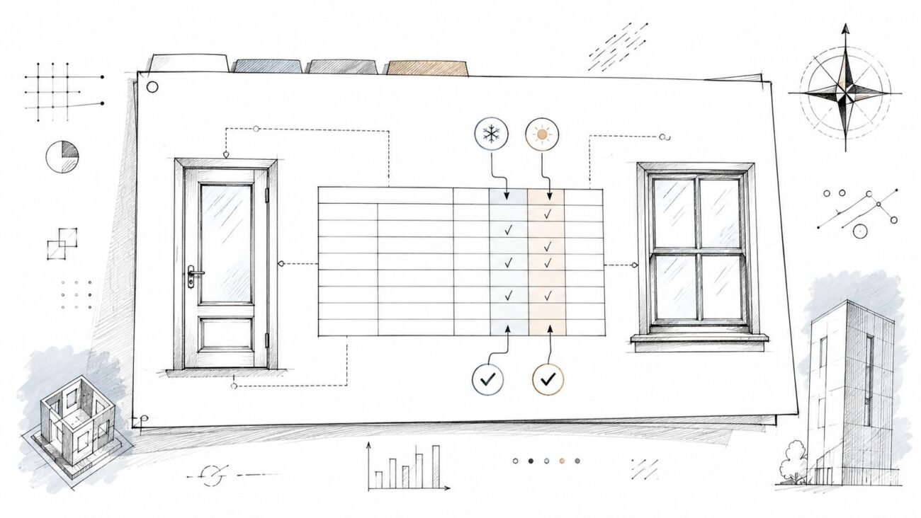
A manufacturer needs exact door and window data, not placeholders dressed up as resolved design.
That includes confirmed width and height, rough opening assumptions where applicable, head and sill relationships, edge distances, and dimensioning from reliable control lines. A window family placed roughly where it belongs may be enough for design coordination. It isn't enough for a production release.
Opening locations should be controlled from stable datums, not from whatever face of finish happened to be dimensioned on the permit set.
Connections, support, and interface conditions
Panelized wall systems expose interface mistakes fast. The panel-to-foundation condition, panel-to-floor edge relationship, panel-to-roof connection, and panel-to-panel joints all need explicit modeling or explicit detail references that leave little room for interpretation.
Manufacturers usually need clarity on:
- Base conditions: Slab edge, curb, stem wall, anchorage assumptions, and shim space
- Vertical joints: Spline, strap, plate, seal, tolerance, and structural continuity strategy
- Lateral interfaces: How panels meet diaphragms, collectors, and adjacent systems
- Embedded or reserved zones: Blocking, electrical chases, and any no-cut areas
Assembly and material definition
Wall type names aren't enough if the production team can't infer the actual build-up to be fabricated.
The model and documentation should make clear the framing logic, sheathing specification, insulation strategy where relevant, and any integrated components that affect machining or assembly. In panelized home construction, a study summarized by Offsite Construction Network on panelized systems reports 26% less lumber, 76% fewer materials going to waste, and 37% fewer labor hours compared with comparable stick-built homes. Those gains depend on disciplined production inputs, not just the choice of system.
Why This Gap Causes Real Delays
A team issues CDs on Friday assuming panel shop drawings can start Monday. By midweek, fabrication has not started. The manufacturer is still waiting on answers about panel segmentation, rough opening control points, base-of-wall tolerances, and which connection detail governs at the floor line.
That delay is not a general coordination problem. It comes from a specific gap between a design-intent BIM model and a manufacturing-ready one.
A design model can be fully coordinated for permit or pricing and still be unusable for production. The geometry may look settled, but the information the shop needs to cut, frame, sheath, label, and ship each panel is still missing or ambiguous. At that point, factory time gets replaced by question logs, marked-up backgrounds, and revision clouds.
The common delay pattern
The sequence is predictable:
- CDs issue with a model that shows wall layouts but not fabrication logic
- The manufacturer maps the walls into panel units and finds unresolved decisions
- RFIs come in on panel breaks, opening dimensions to the wrong reference, allowable shim space, fastening assumptions, and panel-to-panel joint conditions
- The design team and engineer revisit details they treated as complete
- Submittals expand, procurement holds, and the fabrication slot slips
The lost time rarely comes from one major miss. It comes from twenty small ones that block release.
A window may be located to a gridline in the model, while the shop needs a framed opening dimension from panel edge. A wall may be modeled as one continuous assembly, while the manufacturer needs approved break points that account for transport length, lift weight, and field splice locations. A base detail may show anchorage conceptually, while the shop needs slab edge variance, hold-down clearance, and expected shim range before it can finalize panel heights.
Those are not drafting cleanups. They are production decisions.
Why schedule gains disappear
Factory production runs on sequence and commitment. Once a panel release is approved, material gets ordered, CNC data gets generated, and shop space gets assigned. If the model is still carrying unresolved assumptions, the manufacturer either pauses or proceeds with qualifications that trigger another review cycle.
That is where panelized work loses its speed advantage. The field was supposed to receive finished wall units with fewer open questions. Instead, the project adds manufacturing review on top of the normal design review and still ends up making key decisions late.
As noted earlier, published market forecasts point to continued growth in prefabricated wall panels. Growth does not remove the documentation burden. It increases the cost of getting it wrong, because factories schedule capacity around release dates they expect the design team to meet.
The jobs that move cleanly are not the ones with the most detailed-looking models. They are the ones where the model answers production questions before the first RFI is written.
What It Takes to Get a Model Manufacturing-Ready
Manufacturing readiness isn't a software feature. It's a production process.
Teams that do this well move several decisions earlier than they would on conventional framing packages. They also put stricter QA around model content, annotation standards, and decision ownership. That's where BIM for offsite construction becomes less about modeling skill and more about production discipline.
Coordinate with the manufacturer before CDs harden
The best time to learn a manufacturer's expectations is before the drawing set is treated as fixed.
Every manufacturer has its own standards, preferred naming logic, detail library, tolerance expectations, and production constraints. Some want segmentation driven from module repetition. Others prioritize truck loading and field picks. Some need certain connection families represented explicitly in the model. Others can work from disciplined 2D details tied to reliable references.
A solid pre-release coordination pass should settle:
- Panel manufacturer model requirements
- Preferred panel naming and tagging logic
- Opening control dimensions
- Base and top connection assumptions
- Responsibility split between design team, EOR, and manufacturer
Lock geometry earlier than usual
Teams used to conventional wood framing often carry a little flexibility late into CDs. That habit causes trouble here.
If windows, doors, bearing points, and structural interfaces are still moving after panel logic is being developed, the package becomes unstable. Even small late changes can trigger redraws in segmented wall runs, header logic, and shop references.
A simple internal checklist helps. Before releasing for panel review, confirm that:
- Openings are dimensioned from project datums
- Wall types match actual fabrication intent
- Offsets and recesses are modeled intentionally
- No placeholder families remain in panelized wall areas
- Referenced structural and architectural details agree
Model tolerances and interfaces explicitly
A lot of panel delays come from conditions everyone thought were obvious.
They weren't. Slab edge variation, shim allowances, bracket depth, finish build-ups, and out-of-plane alignment zones need clear treatment. This matters even more when thermal performance is part of the envelope strategy. Dextall's discussion of exterior wall panel performance and thermal bridging highlights a frequent blind spot. Entire-system U-factor has to account for fasteners, brackets, and other thermal bridges, and real-world performance can degrade if those details aren't handled carefully.
That issue shows up in modeling too. If the production model doesn't clearly define attachment logic and bracket conditions, teams may think they have a high-performing wall on paper while the actual assembly is drifting away from the intended envelope performance.
Coordination rule: If a field installer could ask "where exactly does this land?" the model or detail set isn't ready yet.
QA the model like a production package, not a presentation model
A manufacturing-ready BIM model needs a different QA pass than a permit model.
Useful QA checks include:
- Panel break consistency: Similar conditions segmented the same way
- Opening verification: Dimensions, host walls, and control locations checked against schedules
- Connection completeness: No critical interface left to generic notes alone
- View reliability: Enlarged plans, sections, and details reference the same geometry the shop will use
- Export readiness: Naming, shared coordinates, and sheet references are clean enough for downstream use
CAD-to-BIM habits can hurt teams. A drawing set can look coordinated while the model behind it still carries unresolved geometry or generic content that won't support fabrication.
Where This Applies Beyond Panelized Walls
A team can get through permit with a clean-looking model, then stall the minute a manufacturer asks for split locations, connection hardware, shipping limits, or install sequence. That pattern is not specific to panelized walls. It shows up anywhere a design model has to become a production package.
CLT projects run into it when the model stops at slab and wall extents but never resolves panel breaks, embed locations, edge distances, pickup points, or penetration ownership. Modular work hits the same wall for different reasons. The model may show the module layout, but production still needs stack-joint tolerances, chassis or frame interfaces, MEP tie-in points, hoisting constraints, and transport geometry defined clearly enough to release fabrication. Log home and specialty kit systems have their own rules, but the handoff problem is familiar. The model looks coordinated for design review, while the manufacturing team is still missing the decisions that control procurement, machining, and assembly.
The useful comparison across offsite systems is not material or brand. It is documentation maturity.
The shared pattern across specialty systems
The same breakdowns keep showing up across these systems:
- Geometry approved before production splits are fixed
- Interface details assigned loosely between architect, engineer, manufacturer, and installer
- Generic model content standing in for actual fabrication conditions
- Tolerance assumptions buried in notes instead of tied to specific joints and connections
- Template and naming inconsistency that breaks downstream schedules, exports, or CNC prep
In practice, delays usually start at the interfaces. A CLT wall-to-floor joint, a modular stack joint, or a pre-cut log corner can all fail for the same reason. The model does not state who owns the final dimension, what tolerance applies, or which connection option was priced and approved.
Teams working across multiple offsite methods usually find the same lesson. Manufacturing does not slow down because the geometry is complex. It slows down because the model leaves production decisions implied instead of explicit.
Where Production Support Fits In
A manufacturing-ready model is a separate production task, not just an extra hour added to design modeling.
That's why firms often pull in dedicated production help on panelized and other offsite packages. The goal isn't to outsource thinking. It's to protect the design team's time while someone with the right BIM workflow discipline carries the panel-specific documentation load, maintains template consistency, and closes gaps before they become RFIs.
There's also a margin angle. UBS research on U.S. building methods and open wall panels notes that converting from traditional stick-built walls to open wall panels can generate roughly +USD 6,175 in total incremental operating profit per house across the value chain, with penetration expected to double to approximately 40% over the next 15 years. Profitability improves when the documentation process supports production instead of fighting it.
Panelized Wall Systems Need Production-Level Modeling
Panelized wall systems only keep their promise when the model feeding fabrication is built for manufacturing, not just for design review. That's the distinction that separates a clean panel release from a stalled submittal log.
Teams usually don't lose time because panelization failed. They lose time because the handoff standard was never defined tightly enough. Once panel breaks, opening control, connection geometry, and tolerance logic are treated as production data instead of late clarifications, the process gets more predictable. RFIs drop. Coordination gets calmer. Fabrication can begin when the schedule says it should.
For firms working across offsite delivery, that same discipline carries into CLT, modular, and other specialty systems. If you'd like a practical framework for reviewing a model before it goes to a manufacturer, BIM Heroes can help with production checklists, QA workflows, and specialty construction support built around real delivery constraints, not generic BIM advice.
Suggested WordPress category: BIM Technology & Workflows
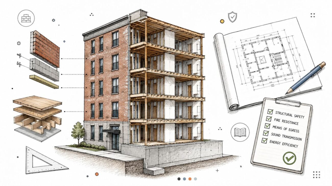
Featured image alt text: Revit-based manufacturing-ready BIM model for panelized wall systems showing panel breaks, opening dimensions, and connection details