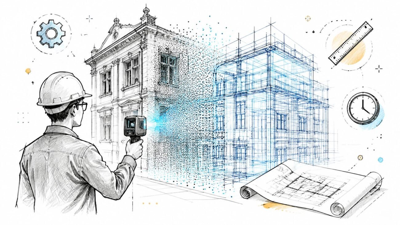
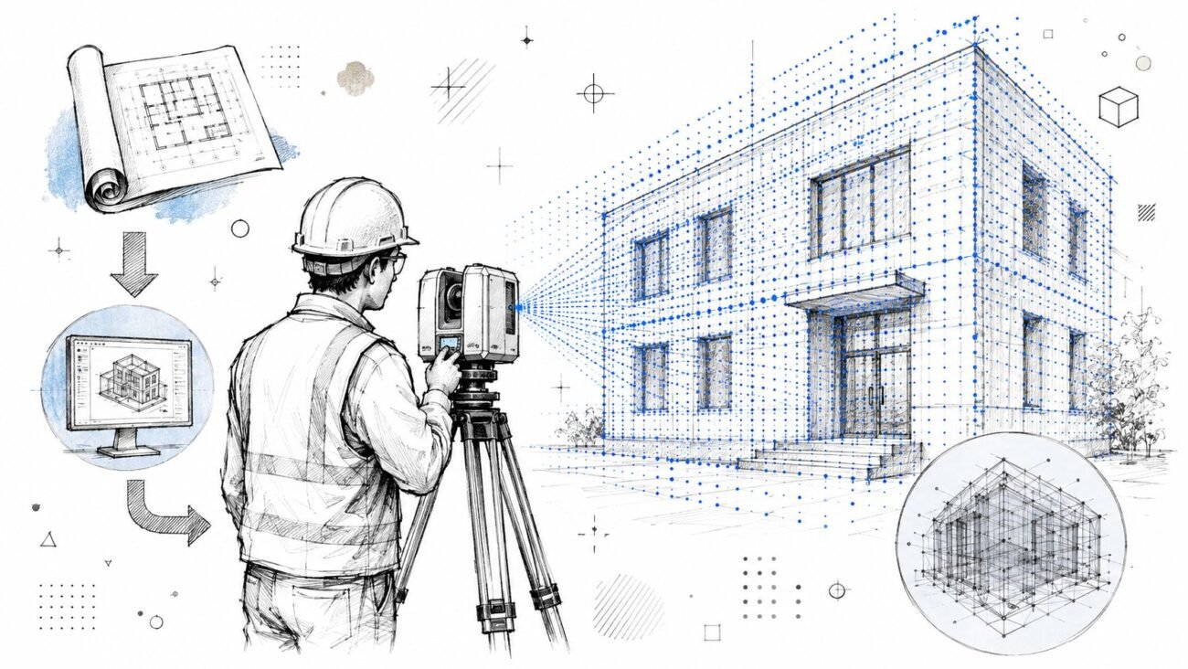
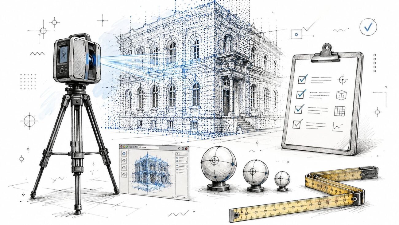
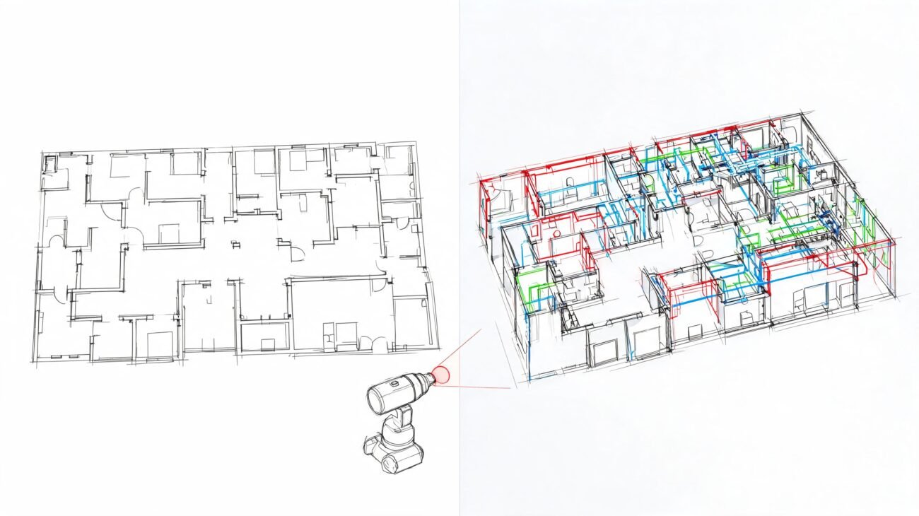
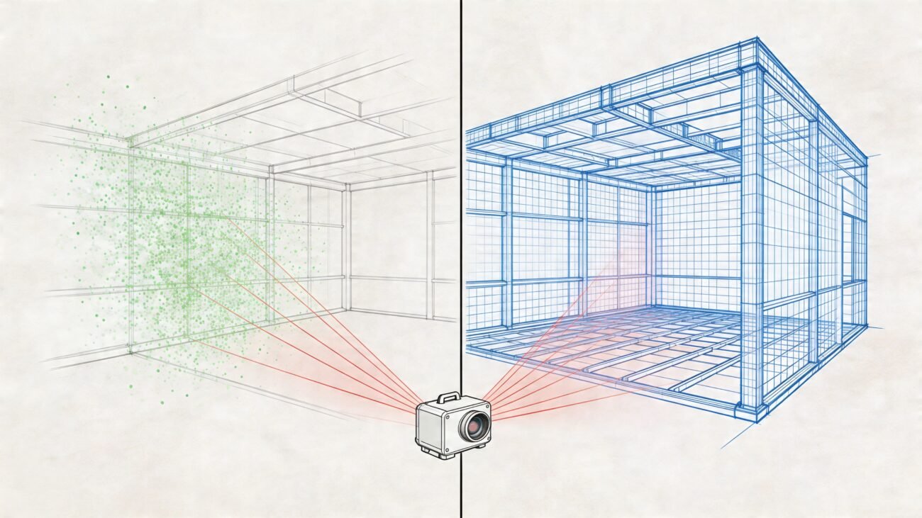
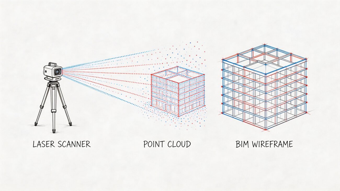
A model that looks right but doesn't hold up in the field can be worse than no model at all. In scan to bim accuracy, the difference between a usable as-built and a liability is whether the geometry was captured, registered, modeled, and verified against the source data. We treat the ±1/8 inch claim as proof, not branding, and the rest of this piece shows how that tolerance is reached, checked, and limited to the conditions where it's defensible. For teams comparing workflows, even a tool like Sculpty's 3D generation tools can make the gap between concept and buildable geometry easier to visualize, but the field standard still comes down to verified reality capture.
Why Accuracy Is the Whole Game in Scan to BIM
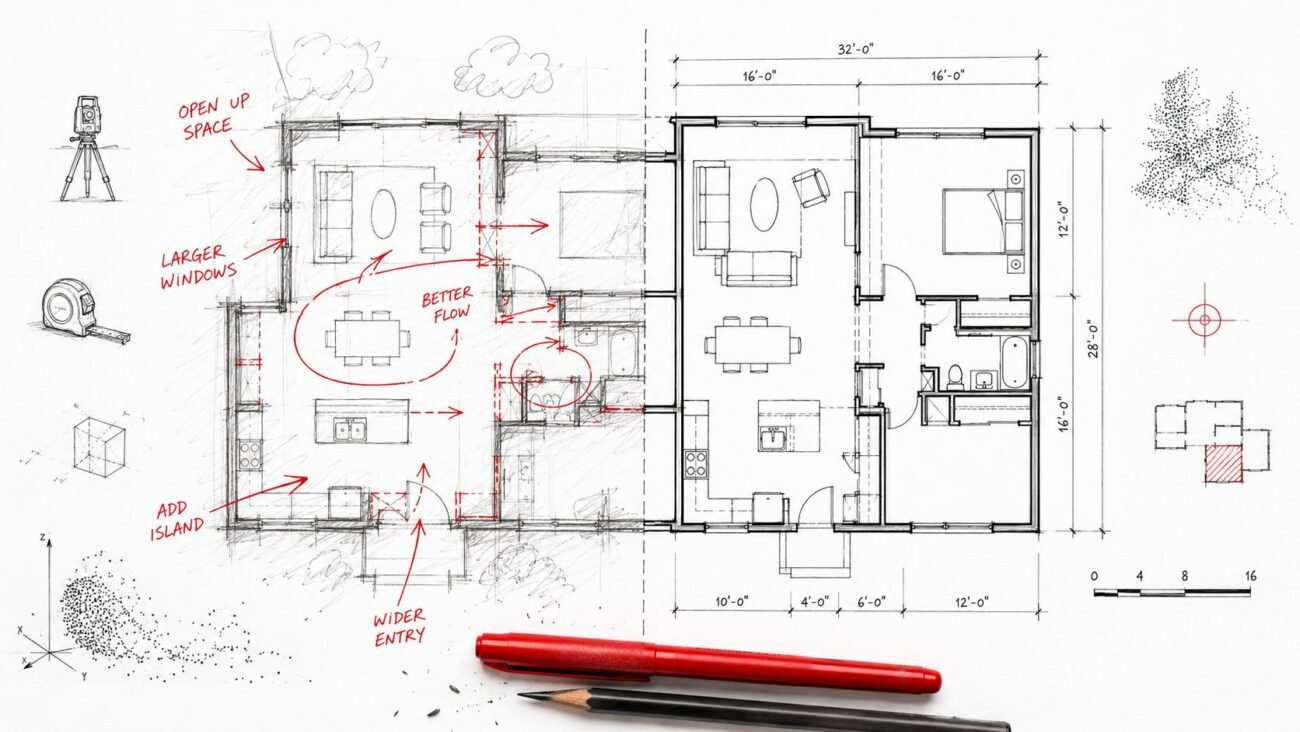
An as-built that can't be trusted creates false confidence. That's the primary risk on renovation and retrofit work, because crews start coordinating, pricing, and prefabbing from geometry they assume is right.
Our position is simple, an unverified model is worse than no model if it sends the wrong team into the field with clean-looking but inaccurate decisions. The ±1/8 inch tolerance we use is tied to a measurable workflow, not a vague promise, and this article shows the process and the check behind it.
For buyers evaluating scan to BIM services, the question isn't whether a model is “accurate” in the abstract. It's whether the capture, registration, and modeling steps were disciplined enough that the model can survive coordination, permitting prep, and downstream fabrication review. If you're also weighing automation in adjacent workflows, the accuracy expectations are very different from the output style used by LiDAR vs photogrammetry comparisons, because Scan to BIM is judged on field-verifiable fit, not just visual realism.
Practical rule: if the team can't show how the model was checked back against the cloud, the number is marketing, not production.
What ±1/8" Tolerance Actually Means
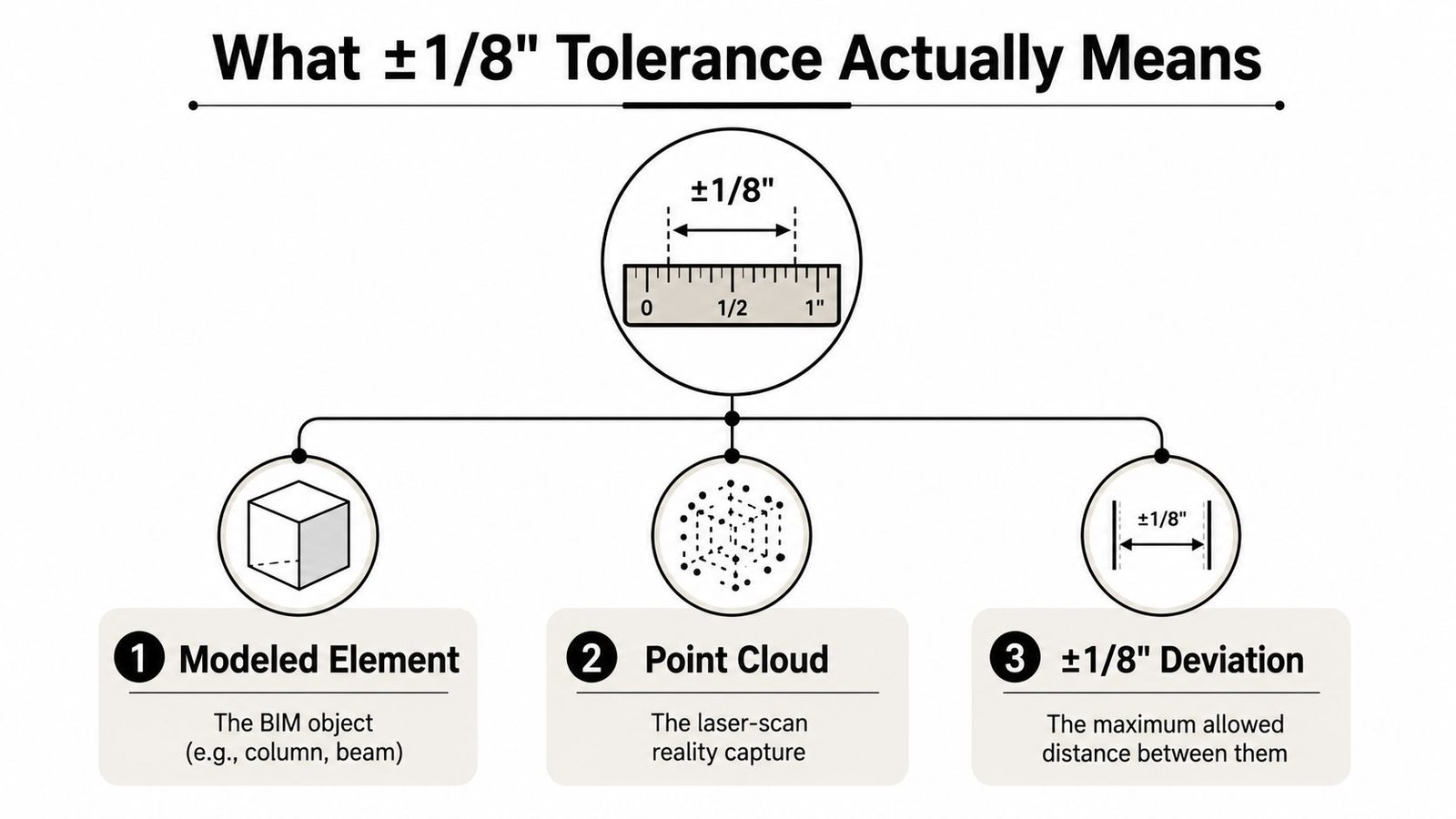
In plain English, ±1/8 inch tolerance means the modeled element sits within one-eighth of an inch of the registered point cloud it was traced from. It does not mean every scanner reading is perfect, and it doesn't mean every surface in every project will be modeled to the same standard.
That distinction matters. Capture accuracy is the quality of the scan and registration process itself. Model accuracy is how faithfully the BIM element is traced and constrained to the processed cloud, which is why Point Cloud to Revit LOD decisions matter so much when scope, time, and intended use aren't aligned.
Where the tolerance applies
We treat the claim as conditional, not universal. It applies when the scope is defined up front, the target LOD is set clearly, and the scanner format is compatible with the workflow, including Leica, FARO, Matterport, NavVis, Trimble, and DotProduct. The practical boundary is this, the tighter the deliverable, the more the team has to control registration, tracing discipline, and verification.
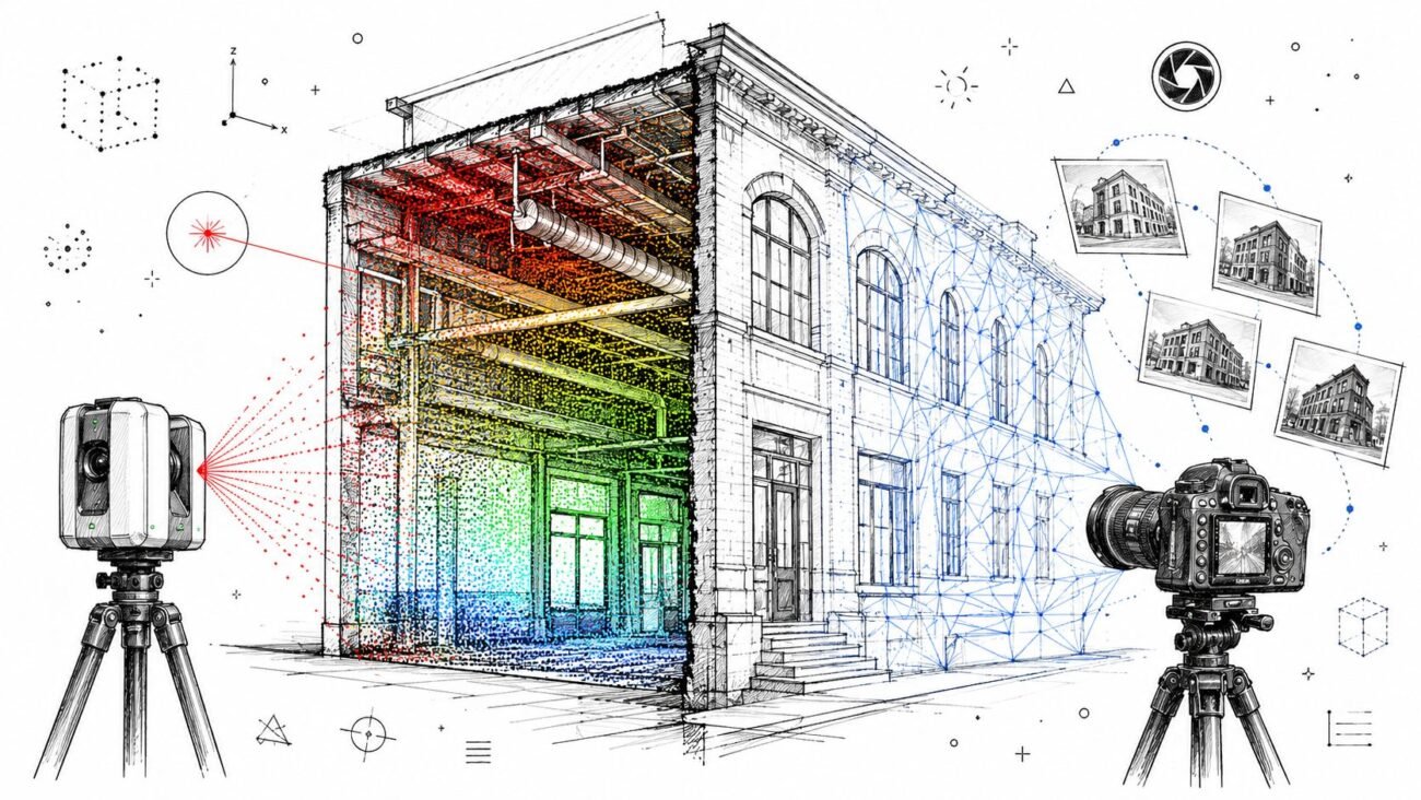
The core workflow is a three-step process, data collection, data processing, and BIM modeling. That sequence is consistent with academic overviews of Scan to BIM and it keeps the claim grounded in the source data instead of in design intent alone.
What Degrades Scan to BIM Accuracy
Accuracy slips long before anyone opens Revit. The most common problem is not a bad modeler, it's a weak field setup that gives the modeler too little to work with or too much uncertainty to resolve cleanly.
The failure points that show up in real projects
- Scanner limits and range drift: every device has a practical envelope, and pushing it too far makes edges softer and surfaces less reliable.
- Registration error: if multiple scans aren't stitched tightly, small offsets become bigger problems across long corridors or large floor plates.
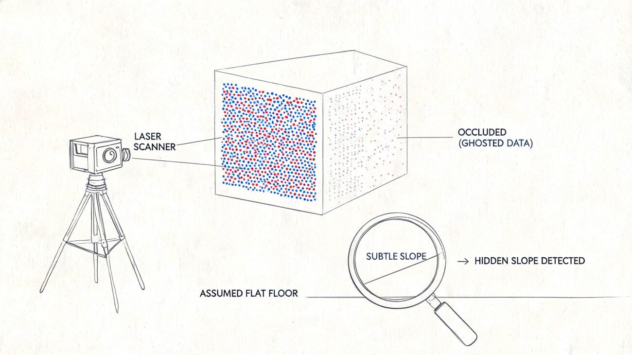
- Occlusion: furniture, equipment, shelving, and dense MEP create blind spots that the cloud can't magically fill.
- Reflective surfaces: glass, polished metal, and shiny finishes scatter returns and can produce noisy or incomplete geometry.
- Thin coverage: too few scan stations leave gaps that get “bridged” by guesswork later.
- Modeling shortcuts: the biggest self-inflicted error is tracing intent instead of tracing what's there.
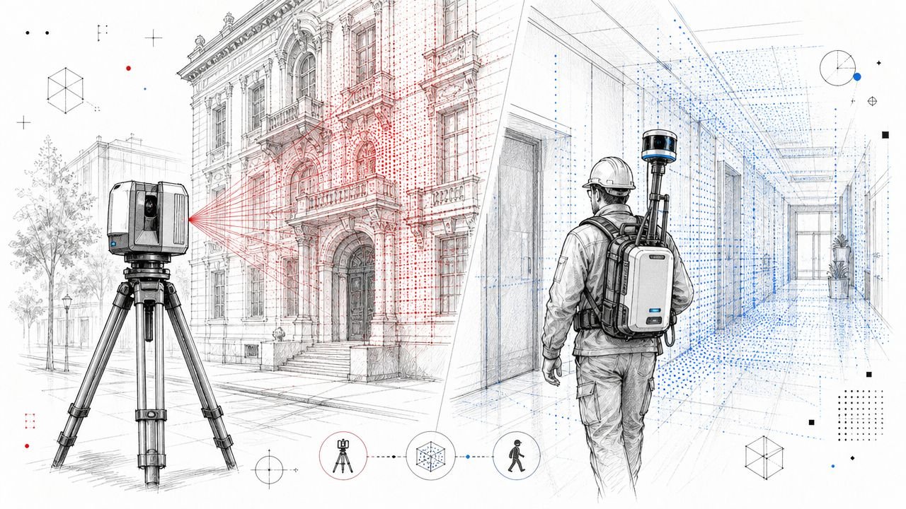
Hard-access and cluttered buildings make this worse, especially in renovations and heritage work where a single ground-based pass won't cover everything. In those cases, hybrid capture is often the smarter answer, because selective follow-up scans can fill occlusions without pretending the first pass saw everything.
A useful comparison is 3D photography examples. Photogrammetry can help in the right context, but Scan to BIM jobs punish assumptions, and geometry that matters for coordination has to be visible, registered, and checked.
The point-cloud side of the workflow depends on disciplined capture. For a more detailed field view, see our point cloud scan reference.
Our Process for Hitting the Tolerance
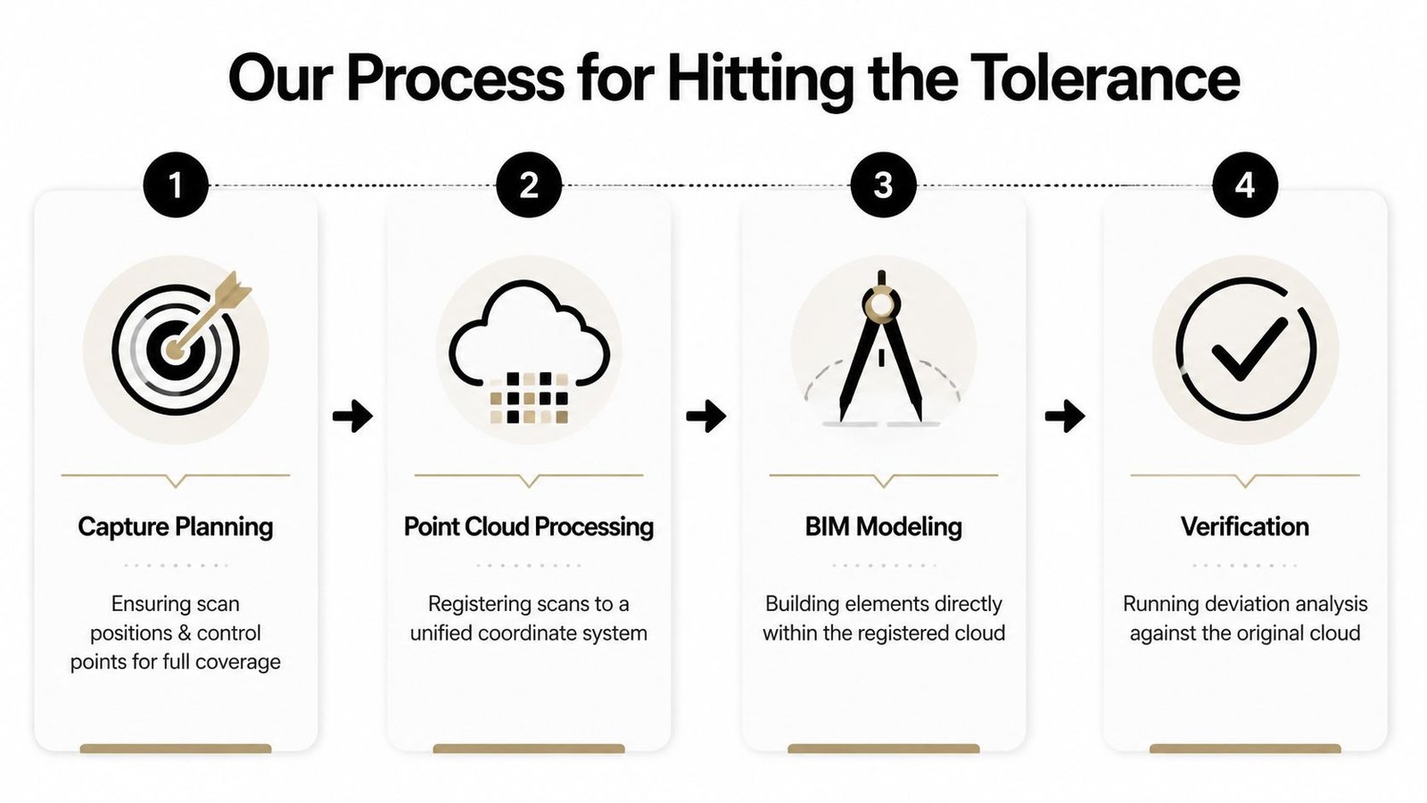
Hitting a tight tolerance starts before anyone opens the model file. The capture plan has to match the end use, because scan spacing, control, and registration quality set the ceiling for what the model can safely claim later.
Capture planning and registration discipline
Survey control is approved before mobilization, and scan positions are laid out to keep blind spots down and registration stable. A practical Tandem guidance document recommends 3 to 7 geolocation control points across a facility, along with point-cloud targets such as point density ≤ 0.5 cm, range accuracy ≤ 0.5 cm, point-cloud accuracy < 2 mm, and overall 3D positional accuracy ≤ 7 mm. Those targets matter because they show how much the field setup shapes the final model's limits. Tandem Scan to BIM guidance
The registration pass is checked before modeling begins. If the scan network drifts, no amount of clean drafting will pull the model back into tolerance, so the field team has to solve that problem while the data is still in hand.
Modeling to the cloud, not to a wish list
Once the scans are processed and registered, the model is built directly against the cloud in Revit, ReCap, Leica Cyclone, FARO Scene, and Navisworks, with point cloud software tools chosen to match the file size, registration method, and downstream deliverable. The workflow stays practical: structural, architectural, and MEP items are traced to the registered data at the agreed LOD, and anything blocked by access or occlusion is marked as approximate instead of being filled in from guesswork.
That discipline protects the budget and the tolerance claim at the same time. A model that follows the registered cloud is easier to defend in coordination, while a model that chases an optimistic drawing set will look tidy and fail the first field check. For a deeper breakdown of downstream detail levels, the companion point cloud to Revit LOD discussion is the right place to see how scope changes with use case.
If a surface can't be seen clearly in the cloud, it shouldn't be modeled as if it was.
How We Verify the Tolerance Claim
Verification is where a claim becomes a deliverable. After modeling, the BIM is compared back to the registered cloud using deviation analysis, so the team can see where surfaces sit relative to the scan data instead of relying on subjective visual fit.
What the QC pass actually checks
The check includes heat maps, spot reviews of critical elements, and a deviation report that ships with every model. We focus the review on the parts that matter most to the client, especially structural edges, MEP penetrations, and tight coordination zones where a small miss can turn into field rework. That's the difference between “looks close” and “meets tolerance.”
A useful way to think about it is like calculating error from the output side, not just the input side. For teams that want a simple conceptual frame, calculate data extraction error rate is a practical reminder that accuracy checks should be tied to measurable output, not assumptions.
Who signs off
The QC pass is handled after modeling and before delivery, so issues are caught while the file is still in production. The person verifying tolerance isn't hunting for style, they're checking whether the model matches the cloud closely enough for the intended use, and whether any approximate areas are clearly called out.
That's why our deviation report on every model matters. It turns the tolerance claim into something a GC, BIM manager, or owner rep can review instead of just trusting.
When ±1/8" Is the Right Target and When It Is Not
Tighter tolerance is not automatically better. It takes more scan density, more processing, and more review time, so the right target depends on how the model will be used.
Best-fit uses for tight tolerance
Use ±1/8 inch when the model has to support critical coordination, facade and MEP routing, clash detection, or fabrication details. Those are the jobs where small offsets become costly quickly, especially in retrofit spaces where existing conditions are already tight. That's also where a disciplined outsourced production pod can help, because the workflow stays consistent even when the field data is messy.
Where a looser target is smarter
For general space planning, as-built documentation, initial design validation, or budget-conscious projects, a looser tolerance can be the better business decision. You still get a reliable model, but you're not paying fabrication-grade effort for a use case that won't benefit from it.
BIM service teams that have processed 500+ scans know this trade-off well, and the right scheduling window matters just as much as the number itself. A 5 to 7 day turnaround makes sense for many scopes, but the more exact the tolerance, the more the team has to respect capture discipline and QC time.
Send Us Your Scan Data for a Free LOD Recommendation
If you need a verified as-built, the right question isn't whether the model looks good. It's whether the tolerance was planned, modeled, and checked the way your project needs. See our point clouds library for more context, then send the scan data for a free LOD recommendation and pricing within 24 hours.
We deliver scan to BIM services in RVT, IFC, DWG, NWD, and BCF, and we work with BIM 360, ACC, Procore, and Bluebeam. That makes the handoff cleaner for teams that need a reliable as-built without rebuilding their internal production stack.
If you've got scan data sitting on a drive and need a model that's checked, documented, and ready for coordination, send it over to BIM Heroes. We'll review the scope, recommend the right LOD, and tell you whether ±1/8 inch is the right tolerance for the job before you commit to production.