Meta description: When scan data and legacy drawings conflict, teams need a repeatable protocol, not debate. Learn a practical system for scan to BIM conflict resolution, field verification, model updates, and clean decision records.
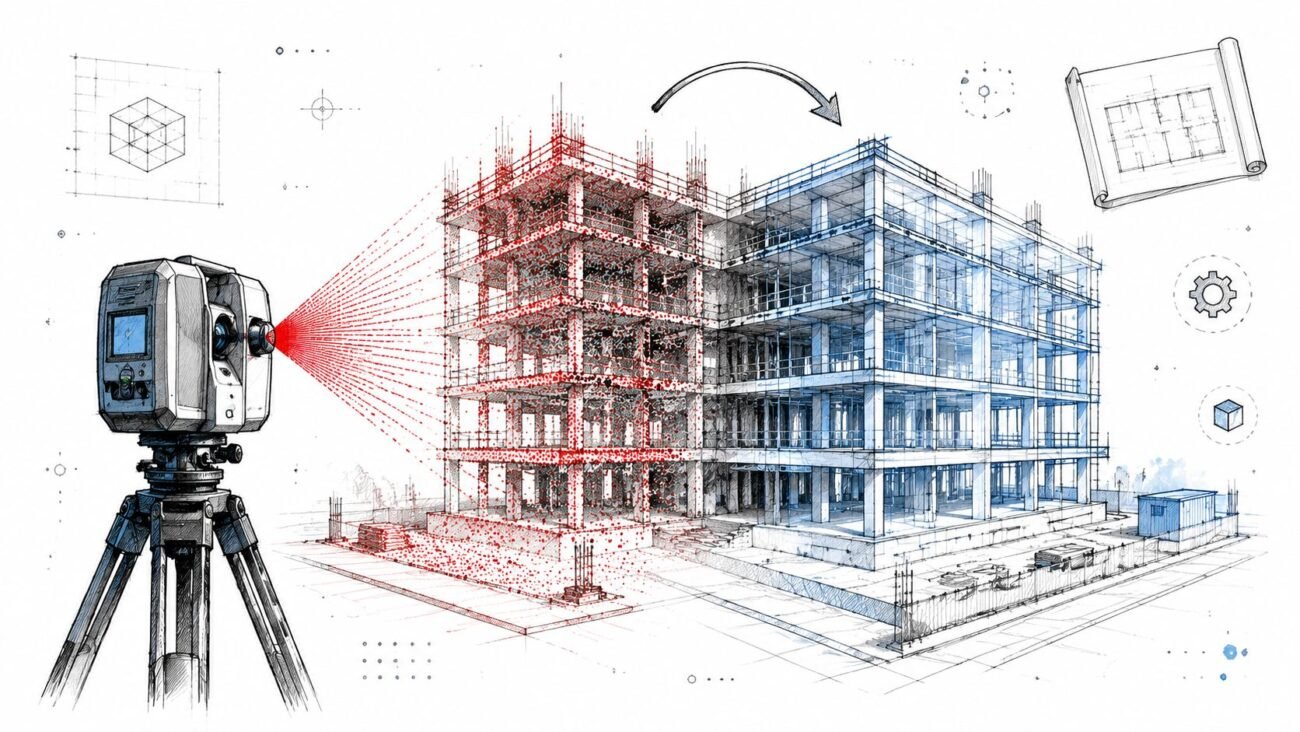
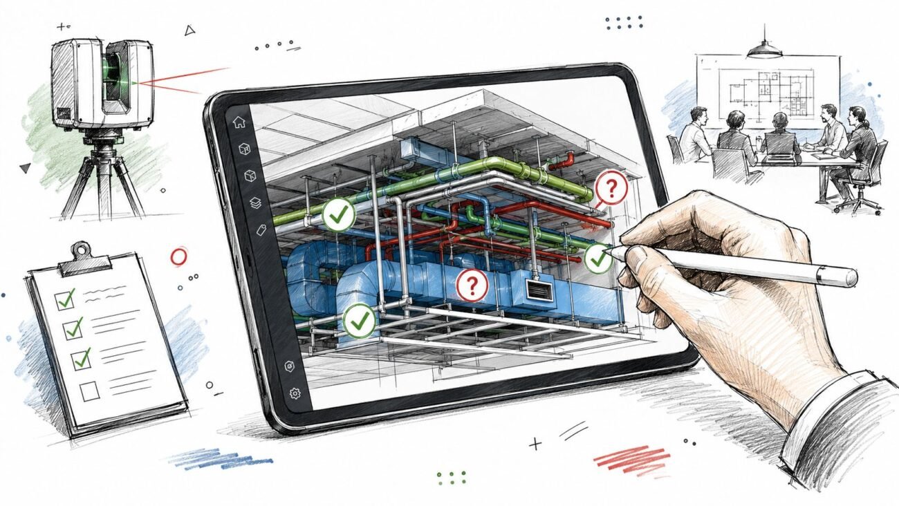
The scan comes back. Registration is complete. The point cloud drops into Revit, and the room everyone thought was straightforward immediately becomes a coordination problem.
A corridor is tighter than the CAD background showed. Ceiling height shifts between bays. A column that was supposed to sit cleanly on grid lands inches off the drawing logic the design team has already started using. Now the project has two competing references and no shared rule for deciding which one governs.
That's where renovation projects start losing time.
The problem usually isn't the scan. It usually isn't the old drawing set either. The problem is the missing protocol between the two. If the team treats every mismatch like a special case, decisions stall, modeling gets inconsistent, and the project record becomes impossible to defend later when RFIs, permit comments, or redesign questions show up.
Scan to BIM conflict resolution works best when it's handled as a standard production workflow. The team needs a way to sort conflict types, assign decision authority, trigger field verification at the right moments, and push approved decisions back into the model without muddying the record. That's how you protect model reliability, keep as-built conditions Revit content usable, and stop minor discrepancies from becoming expensive rework.
Introduction
On an as-built project, the first real friction often shows up after everyone thinks the hard part is done. The site was scanned. The scans were registered. The files are in hand. Then the overlay starts, and the building doesn't behave the way the existing drawings said it would.
Walls drift. Soffits sit lower. Structural elements don't line up with the grid assumptions built into the old backgrounds. At that moment, teams usually ask the wrong question. They ask, “Which one is correct?” The better question is, “What is our decision protocol for resolving this conflict?”
That distinction matters. If you treat each mismatch as a data argument, the production team waits on design, design waits on engineering, and everyone loses confidence in the model. If you treat it as an operational step, the work moves.
This is the field-tested approach that works. Categorize the discrepancy first. Decide who owns the call. Trigger field verification only when the conflict demands it. Then document the decision in a way that keeps the model clean and the project history traceable.
That's the discipline behind good scan-to-BIM services. Not just converting point cloud data into geometry, but creating a controlled path from discovery to decision to model update.
Why Scan to Drawing Conflicts Are Normal
The fastest way to lose control of a renovation model is to act surprised when the scan and the drawings don't match. On existing-building work, that mismatch is standard.
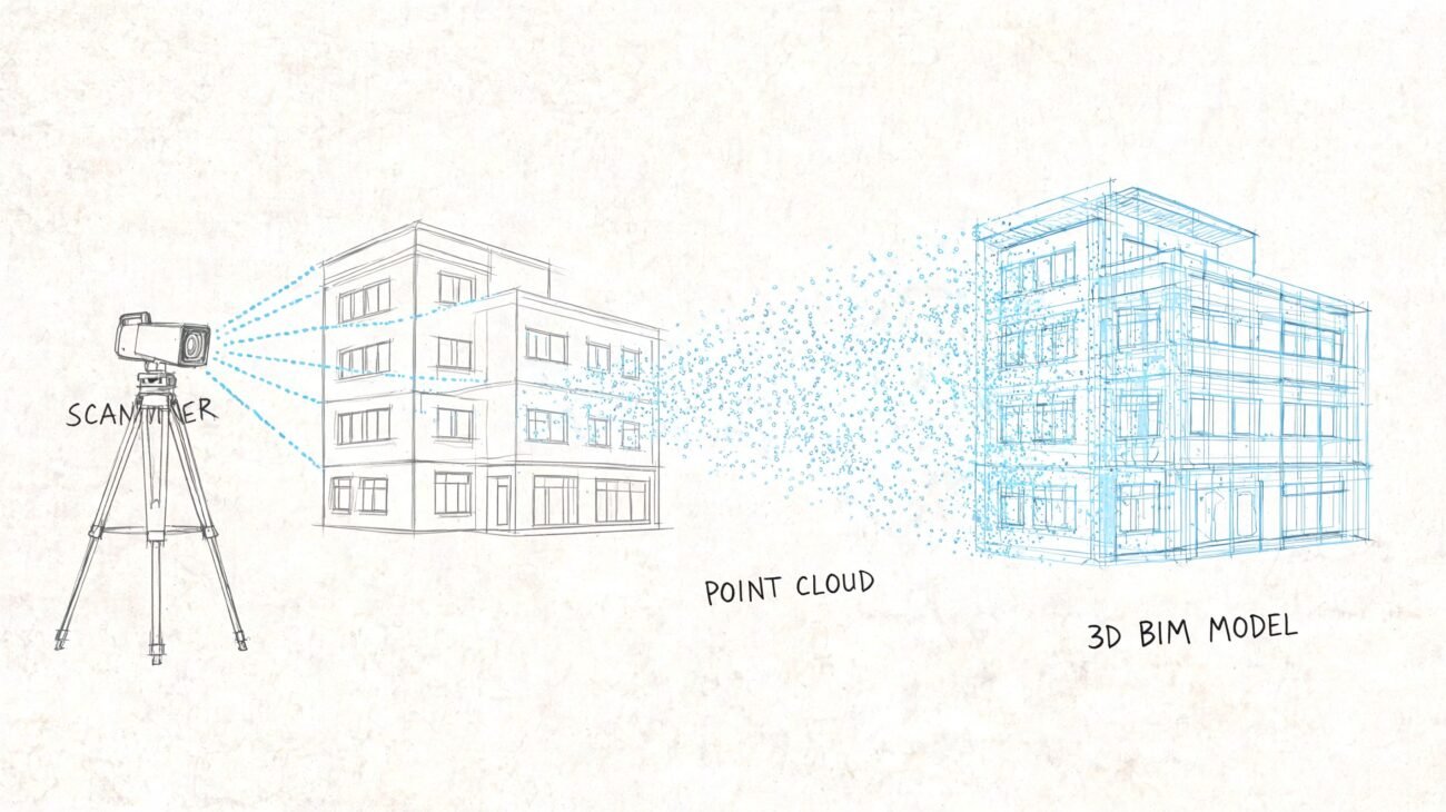
Existing drawings are usually a record of design intent at a moment in time. They are not a continuous history of what was installed, changed, patched, rerouted, removed, or rebuilt over the life of the building. That gap is exactly why scan-based workflows became so valuable. As NavVis explains in its overview of scan-to-BIM, the process captures “as-is” conditions through laser scanning and point-cloud-based modeling, which naturally exposes discrepancies against original documents.
Design intent isn't current reality
Tenant improvements happen. MEP contractors reroute systems in the field. Maintenance teams close openings, replace equipment, and build around old conditions. Some changes get documented. Many don't.
That means as-built drawings vs scan is rarely a clean comparison. One source reflects what someone planned. The other reflects what's physically there today.
The scan measures the building you have. The drawings describe the building the team thought it had.
Tolerances and drawing errors are part of the job
Even if a building followed the documents closely when it was built, real construction introduces dimensional variation. Concrete, masonry, framing, and finish work all produce small offsets that accumulate across long runs and stacked assemblies.
Then there's the older drawing set itself. Legacy files often contain mislabeled dimensions, discipline-to-discipline coordination misses, or geometry that was never updated after a revision cycle.
A practical team keeps both truths in view:
- The scan is physical evidence
- The drawings preserve original intent
- Neither source should govern without a resolution rule
That mindset prevents overreaction. It also keeps the production team from treating every point cloud discrepancy like a crisis.
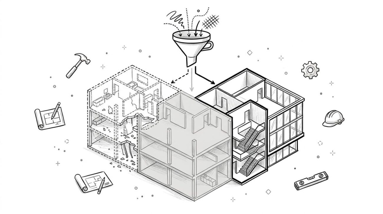
A Practical Taxonomy for As-Built Conflicts
Before anyone decides what to do, the team needs to decide what kind of conflict it is. If all discrepancies get thrown into one bucket, minor issues get over-escalated and serious ones get missed.
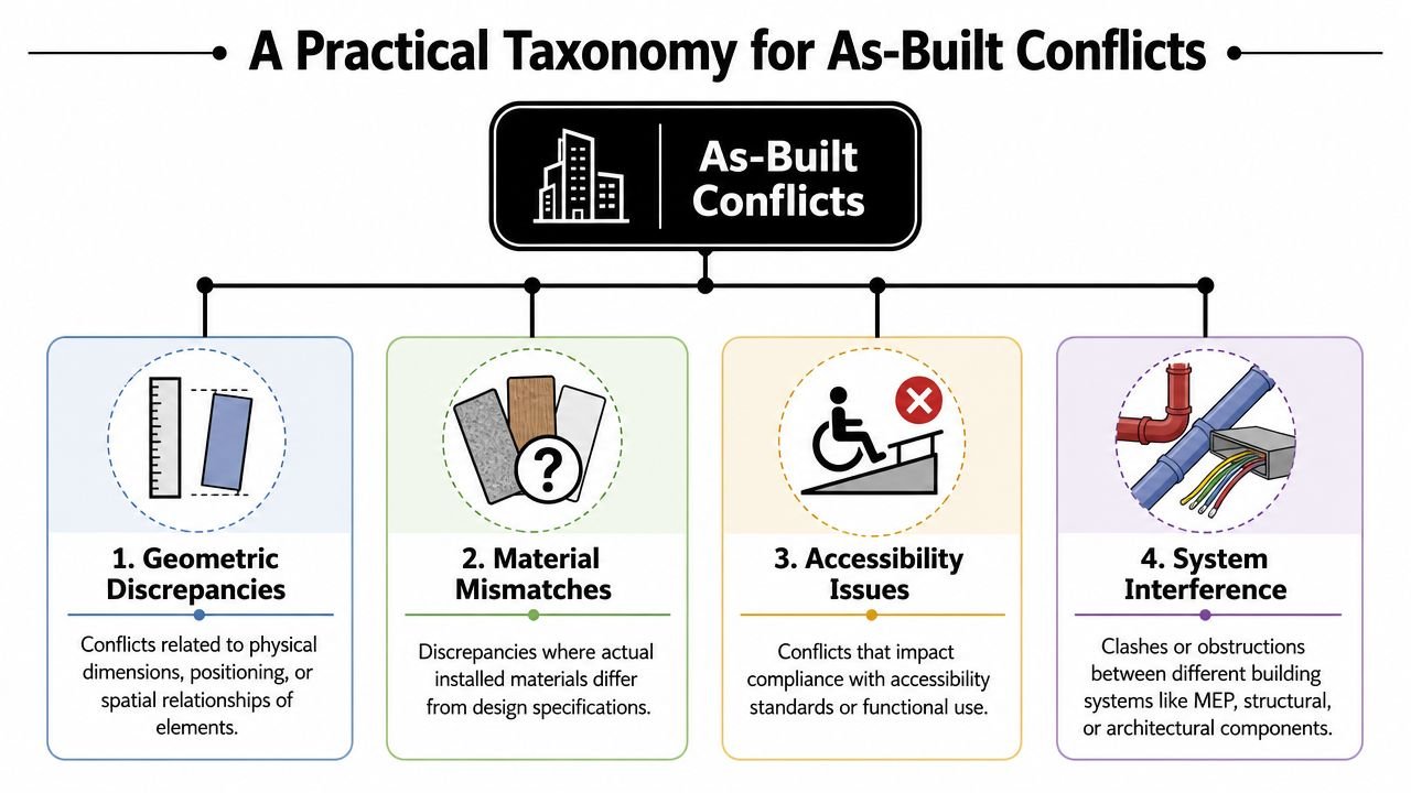
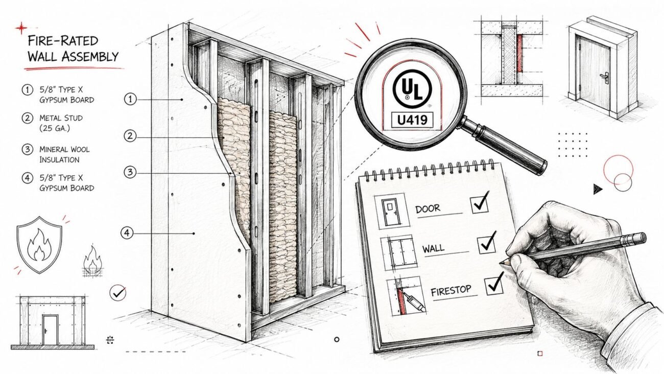
A usable taxonomy starts with tolerance. Tejjy notes typical verification tolerances of about ±2–5 mm against point cloud data. That gives teams a real baseline for separating a small modeling variance from a discrepancy that needs review.
Minor dimensional variance
This is the everyday condition. A wall face is slightly off the drawing dimension. A shaft opening is close, but not exact. The variance is within the project's accepted tolerance for renovation use.
For these, don't create drama. Model to the scan. No escalation. No meeting. No design delay.
In many interiors-focused renovations, this category covers the bulk of what people first notice when comparing point cloud vs existing drawings.
Significant dimensional variance
This is outside tolerance, but it doesn't automatically change structural logic or core design assumptions. Think of a corridor that's narrower than expected, a room width that affects fixture layout, or a ceiling that cuts into planned clearances.
These require review because they can alter how the design develops, even if the condition is still understandable and stable.
Positional conflict
This is different from “a little off.” An element is in a materially different place than the drawing says. A column lands off-grid. A major wall alignment doesn't track with the documented plan. A riser location appears shifted relative to structural or architectural references.
These are the conflicts that can expose registration problems, datum misunderstandings, or legacy drawing errors. Treat them carefully.
Missing or additional elements
These are usually the most consequential. A wall appears in the scan but not in the drawings. An opening is shown in legacy documentation but doesn't exist. Added structure, infill framing, abandoned services, and undocumented enclosures all fall here.
For production teams, this category affects more than geometry:
- Scope assumptions: demolition, retrofit, and permit narratives may change
- Trade coordination: MEP and structure may need re-evaluation
- Model confidence: downstream users need to know this condition was actively resolved
Practical rule: Don't classify by how surprising the conflict feels. Classify by how much decision risk it creates.
The Decision Hierarchy Who Calls What
Projects get stuck when everyone can spot a conflict but no one owns the decision. A workable hierarchy keeps modelers modeling, architects reviewing, and engineers involved only where their judgment is needed.
Cintoo describes scan-to-BIM as documenting existing conditions with millimeter precision and creating a single source of truth for stakeholders. That precision only helps if the team also defines who signs off on which level of discrepancy.
Match authority to conflict type
Use the lightest effective review path.
- Minor dimensional variance: The BIM production team decides. Model to scan and move on.
- Significant dimensional variance: The project architect reviews the implication and approves the modeling direction.
- Positional conflict: The project architect and the relevant engineer of record review it after verification.
- Missing or additional elements: The architect and the affected engineer review it, and client-side visibility may be needed if scope changes are likely.
This hierarchy protects speed. It also keeps the wrong people from making the wrong calls. A modeler shouldn't decide whether a shifted column changes planning assumptions. An architect shouldn't resolve a structural ambiguity without engineering input.
Keep a conflict register
The register doesn't need to be fancy. A spreadsheet is enough if the team uses it.
| ID | Location | Conflict Type | Description | Decision | Decision-Maker | Date | Model Status |
|---|---|---|---|---|---|---|---|
| C-001 | Level 2 East Corridor | Significant dimensional variance | Corridor width differs from legacy drawing | Model to verified scan, PA review complete | Project Architect | 2026-05-22 | Updated |
| C-002 | Grid B-4 | Positional conflict | Column location differs from grid reference | Hold pending field verification | PA + Structural EOR | 2026-05-22 | Open |
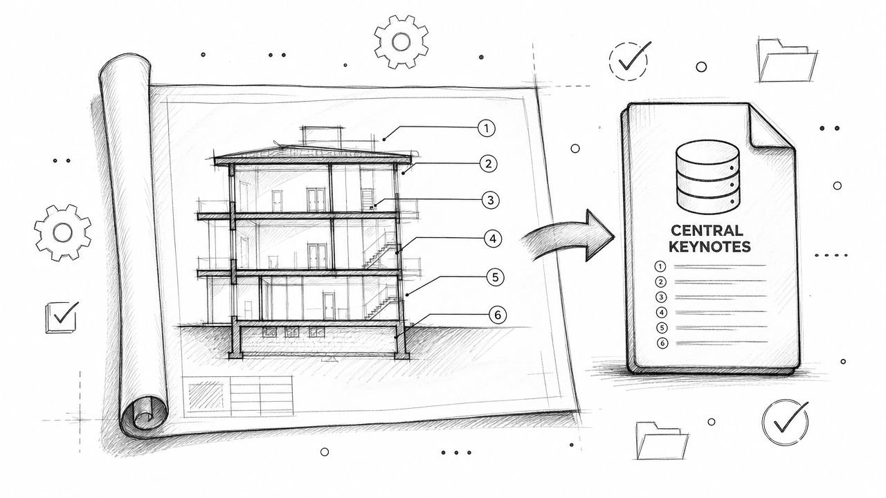
What matters is consistency. Every open issue gets logged. Every decision gets attached to a person and a date. Every model update gets closed out against the same record.
That register becomes the project memory. Without it, teams rely on inboxes, meeting recollection, and marked-up screenshots that no one can find two weeks later.
When You Must Verify in the Field
A coordination team is ready to close a conflict, but the point cloud is thin above the corridor ceiling, the legacy drawing shows a different control line, and the discrepancy affects head height. That is not a modeling judgment call. It is a field verification hold.
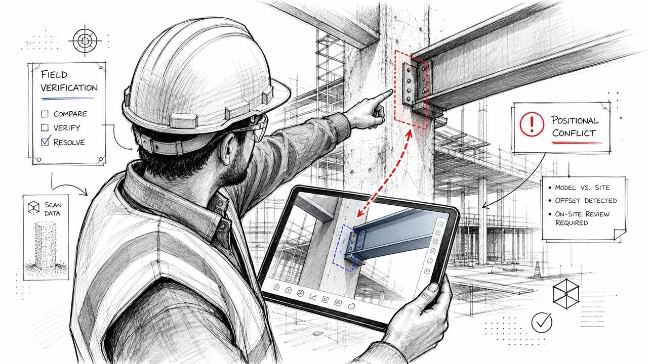
The rule is simple. If the team cannot defend the decision with the scan, the approved tolerance, and the documented scope of use, send it to site verification before the model changes.
ASCE-related guidance summarized by ScanM2 supports that approach. Intended use and tolerance need to be set early, and once a conflict falls outside that limit, or the scan quality is weak in a critical area, field measurement is the safer production step.
Trigger points that justify a site check
Field verification should be a standard checkpoint under these conditions:
- Structural positional conflicts: columns, beams, bearing walls, slab edges
- Code-sensitive discrepancies: corridor widths, head heights, egress paths
- Low-density scan areas: tight above-ceiling zones, blocked rooms, occluded corners
- Tolerance exceedance: the mismatch is outside the project acceptance limit
- Control uncertainty: the scan and legacy drawings may not share the same baseline
Teams that want fewer late-stage arguments usually tie these triggers back to the point cloud scanning process used before modeling begins. Bad decisions often start upstream, with incomplete coverage, poor registration assumptions, or a vague brief on what the model is supposed to support.
What field verification must produce
A site visit only counts if it creates a record the team can trace later. In production, I treat verification as a deliverable with a minimum evidence package:
- Written measurement
- Date of verification
- Name of the person who measured
- Instrument used
- Photo tied to location
- Conflict register update
A verbal site confirmation is not a project record. It is an informal note until someone documents it.
The failure pattern is predictable. A superintendent or modeler checks the condition, reports the result in chat, and the team updates the model. Weeks later, the issue gets challenged during permit review, owner review, or trade coordination. The geometry may still be correct, but the project team has no audit trail showing who verified it, what was measured, and why that decision was approved.
That is where margins get hit. One undocumented field call can trigger a redraw, another review cycle, and a credibility problem that spreads beyond the original conflict. A controlled verification step costs less than rework.
Updating the BIM Model After Resolution
A conflict isn't resolved when the meeting ends. It's resolved when the approved decision is pushed into the model, marked for traceability, and checked for downstream impact.
NavVis describes scan-to-BIM as a data-transformation workflow that turns millions of point cloud data points into a single source of BIM truth. That's the right modeling standard after conflict review. Use the registered scan as the authoritative reference unless the logged decision explicitly says otherwise.
Model to the resolved condition
Once approval is in place, the production team should update the element directly to the accepted as-built condition. Don't leave “temporary” geometry in place waiting for a future cleanup pass. Temporary usually becomes permanent.
For teams refining their production setup, this is the same discipline used in mature point-cloud-to-BIM conversion workflows. The point cloud isn't just a visual underlay. It's the control dataset behind the modeled geometry.
Preserve traceability inside Revit
Use a note, shared parameter, or agreed model flag on elements that changed because of a resolved scan conflict. That gives the design team immediate context during planning and documentation.
A clean protocol usually includes:
- Element flagging: mark geometry updated from verified scan conflict
- Reference retention: keep original drawing geometry in a linked file or reference workset
- Architect review cue: flag any resolved change that affects dimensions likely to appear in CDs
Many teams confuse model correction with documentation correction. They are not the same task. The BIM model may now reflect the right as-built condition, but room dimensions, ceiling notes, enlarged plans, and permit sheets still need coordinated review before issue.
Communicating Key Conflicts to the Team
The conflict register is for internal control. It is not the thing you forward to the client and hope they interpret correctly.
What the design team and client need is a short decision-oriented summary. The message should identify the conflict, explain why it matters, and state what action or acknowledgement is needed. Anything else creates noise.
Report impact, not raw discrepancy
A wall being slightly off usually doesn't deserve executive attention. A structural deviation that changes planning assumptions does.
The better format is a filtered summary by impact:
- Design implication: does this alter layout, clearances, or renovation feasibility?
- Coordination implication: does it affect structure, MEP routing, or fabrication assumptions?
- Documentation implication: does it require a change before the next issue set?
If the team is already managing model coordination through a structured clash detection workflow, use the same communication discipline here. Don't dump model findings. Route decisions.
Give stakeholders a clear ask
A useful conflict memo ends with a decision request. Review revised layout. Confirm scope change. Approve additional verification. Update planning assumption.
The strongest conflict reports don't just say what was found. They make the next decision obvious.
That framing protects momentum. It also keeps the client from getting buried in technical detail that doesn't affect scope, schedule, or design direction.
Preventing Conflict Overload on Your Next Project
The easiest conflict to manage is the one you scoped correctly before the scanner ever arrived. Teams often think conflict volume is mainly a building problem. It usually starts as a planning problem.
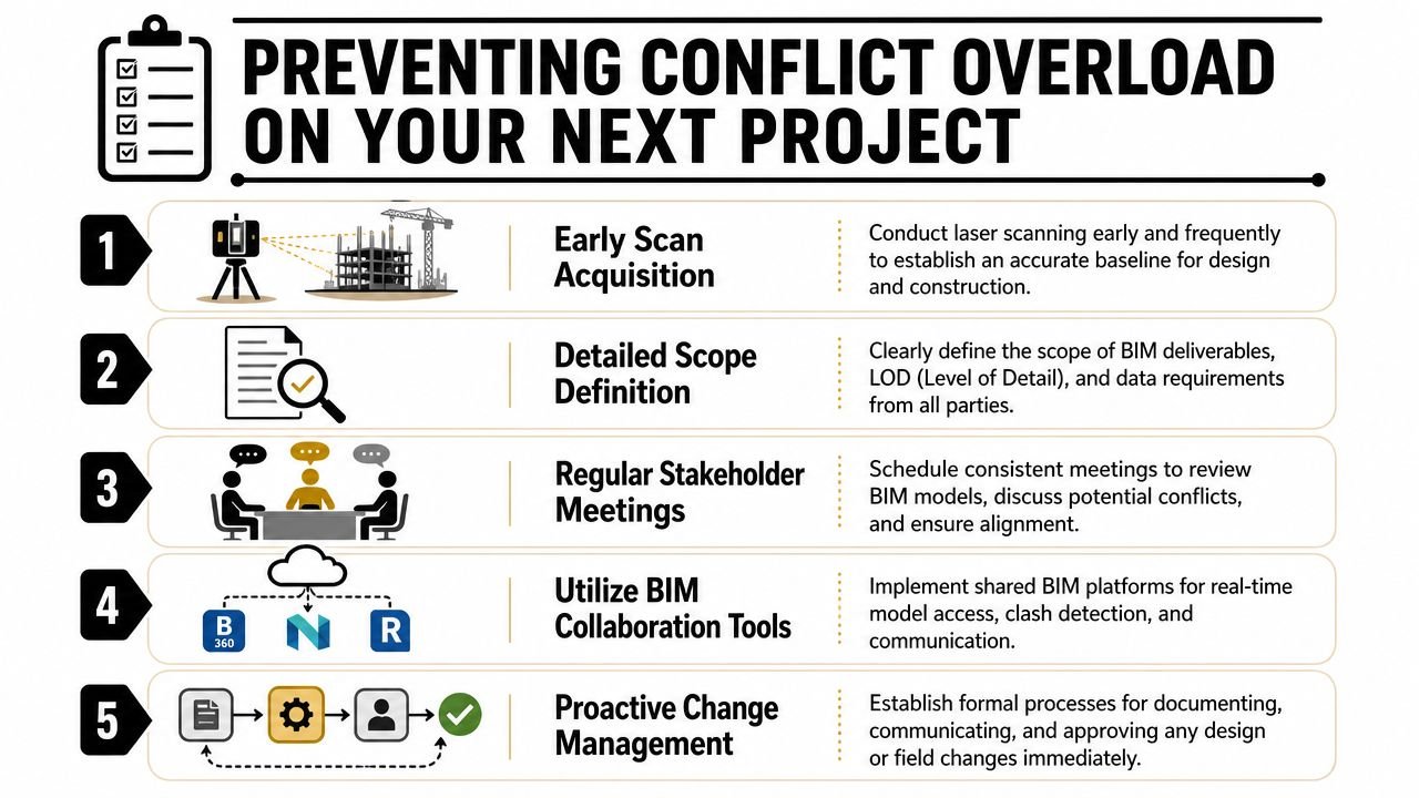
Set the rules before capture
If tolerance, intended use, and model purpose are vague, every discrepancy turns into a debate. If those rules are agreed early, the production team can sort routine variance from real risk without waiting for constant input.
A tighter setup includes:
- Defined tolerance thresholds: what gets modeled to scan, what gets escalated
- Priority scan zones: structure, code-sensitive corridors, critical ceiling spaces
- Prebuilt backgrounds: existing drawings loaded into the model before scan comparison
- Scanner briefing: tell the capture team where conflict sensitivity is highest
Build the workflow, not just the model
Mature scan-to-BIM services separate themselves from one-off drafting support. The value isn't only in producing an RVT from a point cloud. The value is in creating a repeatable system for QA, review, escalation, and handoff.
When teams do this well, they stop treating point cloud discrepancy review as surprise cleanup. It becomes a normal production checkpoint. That shift protects schedule, keeps the project record usable, and gives architects and BIM managers something they can trust when renovation decisions get tighter.
If your team needs a cleaner operating model for scan-based renovation work, BIM Heroes can support the production side with structured Scan to BIM services. If helpful, reach out for a practical framework, conflict register template, or delivery checklist that helps your team resolve as-built issues without dragging rework through the rest of the job.
Category: Construction Coordination & Documentation