Meta description: Timber connection details fail when drawings leave hardware, bearing, fire protection, or model geometry open to interpretation. Here's what a production-ready set must show to prevent RFIs and shop drawing rework.
The rejection comes back fast.
The structural engineer redlines the fabricator's shop drawings because the timber connection shown in the submittal isn't the one the structural set required. The hold-down hardware type changed. The bolt pattern shifted. The bearing plate size wasn't shown in the design drawings at all, so the fabricator filled in the gap with a standard house detail. Now everyone loses time arguing about whose assumption caused the problem.
That failure usually isn't about competence. It's about incomplete instructions.
On mass timber work, the drawing set has to do more than suggest intent. It has to define enough geometry, hardware, bearing, and protection requirements that the fabricator can produce compliant shop drawings without inventing the connection. If your set leaves room for structural guesswork, you've already created the next RFI, the next schedule slip, and the next avoidable cost hit.
Introduction
The familiar version goes like this. The fabricator submits connection shop drawings based on a standard detail they've used before. The engineer reviews them and sends them back because the project needed a different hardware assembly, a different fastener layout, and a bearing condition that was never fully drawn.
That's not a shop drawing problem. It starts in the contract set.
Mass timber projects punish vague documentation faster than steel or concrete jobs do. If the set doesn't show the actual connection logic, someone downstream will fill the gap with a substitution, a workaround, or an assumption. None of those help the design team, and none of them help the schedule.
A solid set of mass timber connection details drawings gives the fabricator enough information to verify capacity, geometry, and constructability without redesigning the connection in the submittal phase. That's the standard worth aiming for.
Practical rule: If a fabricator has to guess at hardware geometry, fastener layout, or bearing requirements, the design set isn't done.
Why Mass Timber Connections Demand More Detail
Steel teams have a mature shared language. A standard steel connection callout often gets you most of the way there because the fabricator, engineer, and detailer are working from established norms. Mass timber doesn't work that way.
The connector market has expanded quickly, which tells you where the pressure is landing. The global timber construction connectors market was valued at USD 968.3 million in 2022 and is projected to reach USD 1,601.26 million by 2026, with a projected 13.6% CAGR, according to Grand View Research's timber construction connectors market report. That growth matters because connections are no longer a boutique issue. They're a core production issue.
Why copied details fail
A timber connection isn't just a shape. It's the interaction of species, hardware system, fastener behavior, load path, moisture exposure, and fabrication method. Swap one of those variables and the detail can stop working as intended.
A connection that works in one timber species may not behave the same way in another. A concealed hardware system from one manufacturer won't necessarily map cleanly onto another manufacturer's geometry or installation requirements. If the set says “provide timber connector per manufacturer,” you haven't made a design decision. You've outsourced it.
What the set has to remove
A complete set removes ambiguity in the places where fabricators usually default to standard practice:
- Hardware selection that's left generic
- Bearing conditions that are shown graphically but not dimensioned
- Fastener patterns that appear diagrammatic instead of engineered
- Pocket and notch geometry that exists in elevation only
- Protection requirements that are implied but not drafted
Here's the core margin issue. An incomplete glulam beam pocket detail isn't neutral. It shifts engineering risk downstream and guarantees a coordination loop back upstream.
If your detail shows beam pocket bearing but omits the bearing plate, hardware type, and bolt pattern, you haven't documented a connection. You've documented a question.
Critical Connection Types That Require Explicit Details
Some connections carry more load, some are more exposed, and some are more likely to create RFIs. On mass timber projects, all of them need clear instructions, but a few categories consistently drive the most rework.
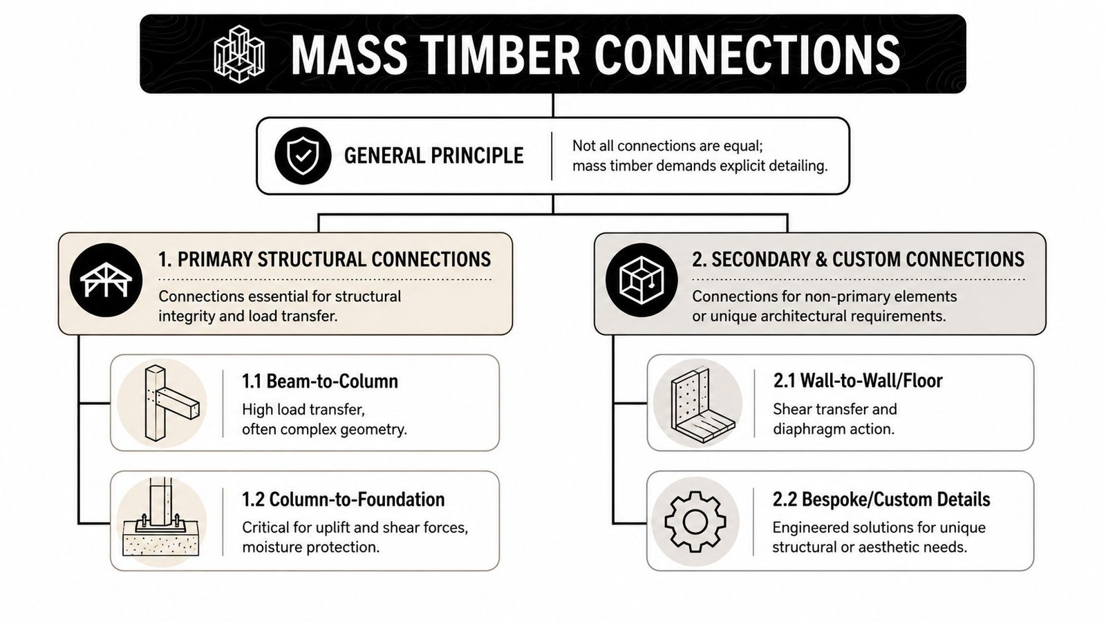
WoodWorks separates mass timber connections into Class 1 systems that use only mass timber elements and structural fasteners, and Class 2 systems that use custom fabricated steel components, as described in WoodWorks guidance on the index of mass timber connections. That distinction matters in production because Class 2 details usually need much tighter documentation around stress concentration, fit-up, corrosion protection, and installation sequence.
If your team is also coordinating panelized systems, the documentation logic needs to align with the broader assembly strategy used in CLT timber panel workflows.
Column base conditions
Column base details fail when they're treated like generic post bases. They need the actual base plate dimensions, anchor bolt pattern, column cap or knife plate reference, and the defined bearing area. If the timber sits above concrete, the detail also needs to make the separation and moisture management legible.
Don't leave the base as a symbolic plate with “see structural.” At the base, uplift, shear transfer, tolerance, and water exposure all collide.
Beam to column workhorse details
This is the connection family that most often gets underdrawn.
The set needs to show the selected hardware type, fastener pattern, any required notch or slot geometry, and the actual load path. If the design relies on concealed steel, show how it fits inside the timber member and what clearances the fabricator must maintain. If the connection is meant to stay simple and fastener-only, show that clearly too.
Beam to beam and roof geometry
Ridge, hip, valley, transfer, and moment conditions deserve their own details. These aren't variants you want the shop to “develop.” The geometry usually gets tighter, the access gets worse, and the fastening sequence becomes less forgiving.
A partial section and one plan callout usually won't cover it. Draw the intersection in the orientation the shop will fabricate from.
CLT panel bearing and edge attachment
CLT panel-to-beam details need more than a line showing panel support. Show the bearing length, edge hardware, interface condition, and any required treatment where exposed structure creates fire or durability implications.
For CLT connection construction documents, that means the panel edge condition has to be as explicit as the support below it.
Anatomy of a Production-Ready Connection Detail
A production-ready detail reads like fabrication instruction, not design shorthand. If the detail can be interpreted three ways, the field will eventually see all three.
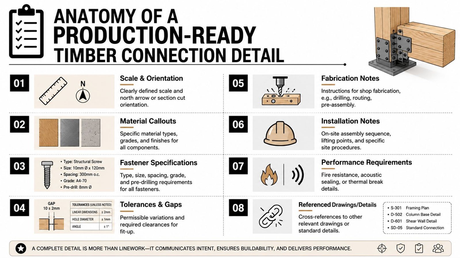
The baseline discipline is simple. Every connection detail has to answer four questions clearly. What hardware is used. How it's fastened. What bears on what. What geometry the timber fabricator is expected to cut.
Teams doing related framing packages usually already understand this from wood framing construction documentation. Mass timber just raises the cost of getting it wrong.
What must be named
Generic notes are where submittal drift begins.
Use the actual manufacturer reference and catalog identification for the hardware. “Timber connector,” “concealed plate,” or “hold-down” isn't enough. The fabricator needs the exact product to validate dimensions, installation constraints, and compatibility with the engineered load path.
Then lock the fastener schedule to that hardware. A complete schedule includes bolt or screw type, size, length, spacing, and any special installation requirement that affects fit or capacity.
What must be dimensioned
Bearing is not an architectural preference. It's a structural requirement, and it has to be dimensioned where it occurs.
The same goes for pockets, notches, slots, and rebates. A lot of sets show the idea of a pocketed beam but don't show the actual pocket dimensions, beam end geometry, tolerances, or any local reinforcement note. That gap is where fabrication assumptions show up.
A useful self-check is this:
- Bearing length shown on every support condition
- Pocket width and depth shown where framing enters a receiving member
- Edge distances and end distances readable at the fastener group
- Clearance for tools and installation considered, not implied
What must be physically possible
Some details fail before anyone checks a calculation because the timber section is too thin for the fastener strategy shown. A technical guide summarized by Calcs.com's introduction to timber connections in structural design notes that structural screws are commonly recommended only when timber members are at least 45 mm thick under AS 1720 guidance, and gives a U.S. structural screw example requiring about 38 mm of member thickness for full embedment and reduced withdrawal risk. If the detail ignores member thickness, the detail is incomplete.
That's exactly why production teams need to review details as buildable geometry, not just linework.
“Timber connection details should be checked like shop instructions. If the installer can't tell what gets cut, what gets drilled, and what gets protected, the detail isn't ready.”
What gets missed at the end grain
Exposed end grain is where moisture and fire vulnerability often get ignored in the rush to issue. If the member end is exposed at a support or penetration, the detail should show how it's protected. Don't assume a general notes page will cover it. Tie the requirement directly to the condition.
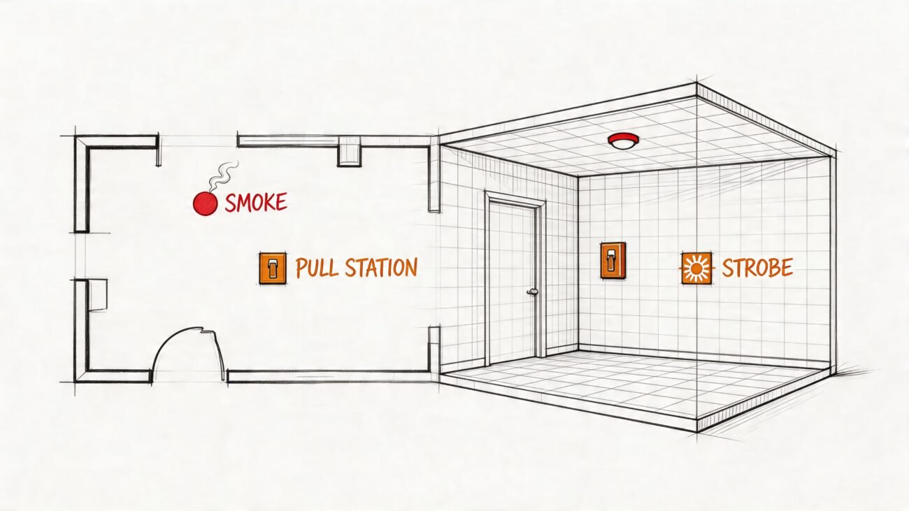
Documenting Fire Performance at Connections
On exposed timber projects, the connection is often where the fire conversation gets serious. A member can have the right overall size and still lose compliance locally because the connection interrupts the protective timber section.
Show how the connection preserves the section
For Type IV work, your detail needs to show how hardware is protected or how the remaining timber section stays compliant where hardware is introduced. That might mean recessed and plugged hardware, a protected cover condition, or an engineered approach that accounts for the residual section after charring.
If hardware cuts into the member, the detail should make that reduction visible. Hidden steel isn't harmless just because it's concealed. If it changes the remaining timber geometry, it has to be documented and checked.
Make the protection strategy explicit
There are only a few acceptable ways this usually gets handled in the drawing set, and each one needs to be legible:
- Recessed and plugged hardware where the timber cover is part of the fire strategy
- Protected connection zones using a fire-rated covering assembly
- Engineered residual section approach where the connection is documented to maintain required performance
- Intumescent treatment where product and application thickness are specified in the detail set
Don't bury this in a note that says “fire protection as required.” That wording guarantees a plan review comment.
Tie permit logic to the detail sheet
A glulam connection detail permit package should let the reviewer see where the connection interrupts the timber profile and how the protection method resolves it. The more exposed the structure, the less tolerance there is for implied compliance.
Field lesson: Fire protection at connections should be visible in the detail itself, not inferred from a specification section that nobody has cross-referenced on the sheet.
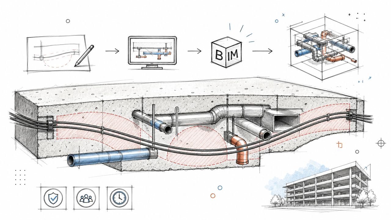
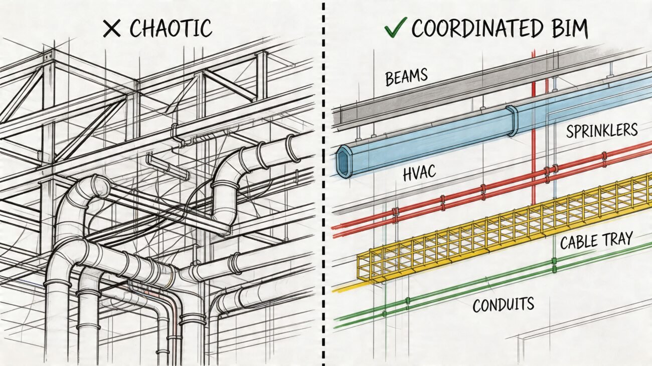
BIM Coordination for Clash-Free Timber Connections
A polished detail sheet won't save a bad model. If the BIM model shows timber members as clean prismatic sticks while the drawings call for plates, pockets, notches, and concealed hardware, your clash results are fiction.
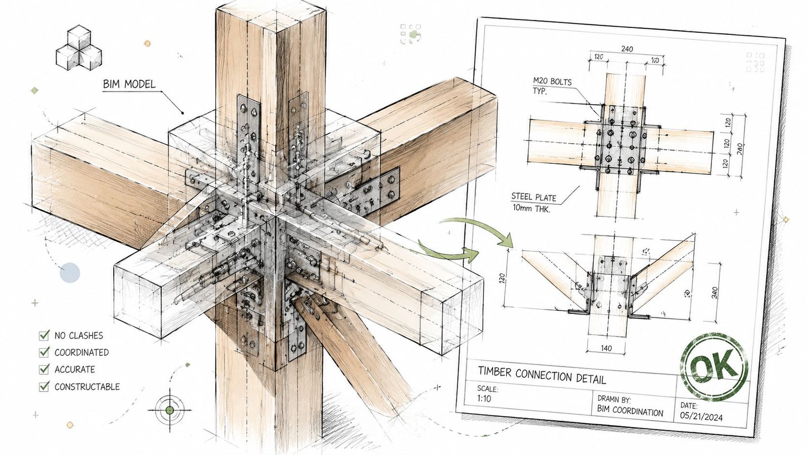
Mass timber BIM coordination has to model the space the connection occupies. Not every washer and screw needs to become fabrication-grade geometry in the authoring model, but the clearance envelope does.
What the model must include
At minimum, the model should represent:
- Hardware clearance zones for concealed plates, caps, shoes, and knife plates
- Pocket and notch geometry in the receiving member
- Real bearing conditions so support length can be verified
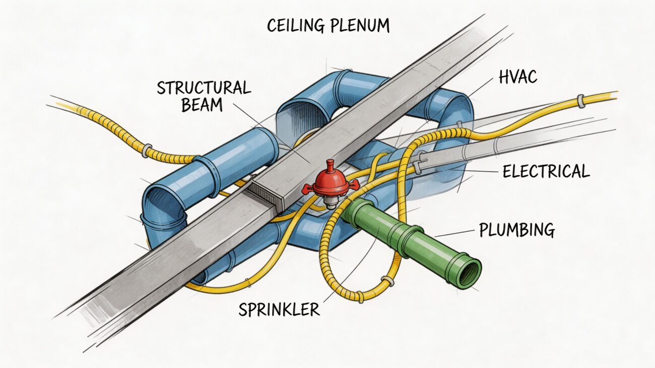
- Conflicting penetrations from MEP, fire protection, and adjacent steel
If the beam is modeled without the notch that the shop will cut, you don't have a coordinated beam. You have a placeholder.
Where serviceability enters the model review
Connection review isn't only about collision detection. Research on timber-concrete composite specimens described hysteretic behavior as “shuttle shaped,” with pinching caused by slip between timber and concrete, and observed angle-steel connector failure by bending deformation and local embedding of the wood during compression, as discussed in BioResources research on hysteretic performance of angle-steel connections. For production teams, the point isn't to turn every model review into a research seminar. The point is to remember that a connection can clear geometrically and still create poor real-world behavior if the detailing ignores slip, crushing, or deformation compatibility.
That insight belongs in model annotations, review comments, and connection schedules where it affects selection.
A QA sequence that works
Before shop drawings go out, run a targeted coordination pass focused on connection zones:
- Confirm geometry against the structural detail and section cuts.
- Verify support length anywhere members bear on timber, steel, or concrete.
- Check concealed hardware volumes against penetrations and finishes.
- Review access for installation tools and sequencing.
- Freeze approved connection families so late substitutions don't inadvertently alter geometry.
That's the difference between a federated model that decorates the job and one that controls risk.
Common Deficiencies That Derail Mass Timber Projects
The same failures show up over and over. They're predictable, which means they're preventable.
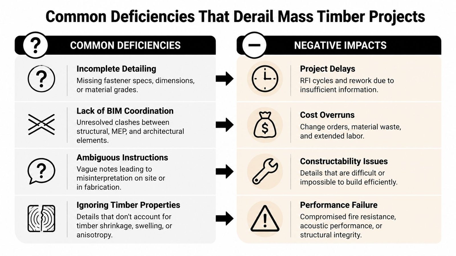
The repeat offenders
-
Generic hardware callouts
“Timber connector” is not a specification. Name the hardware by manufacturer and exact product reference. -
Missing fastener schedules
Every connection detail needs the fastener type, size, length, spacing, and arrangement. If the schedule is missing, the connection is still being designed. -
Bearing not shown
Add minimum bearing dimensions at every support condition. Don't leave bearing to be inferred from linework. -
Undrawn notch and pocket geometry
If a beam frames into a notch or pocket, show the cut geometry in enough detail for fabrication and model verification.
The problems teams miss until late
-
Fire protection omitted at exposed connection zones
If the project relies on protected hardware, plugs, covers, or coatings, show it directly at the condition. -
Connection hardware absent from the BIM model
Clash detection can't catch what the model doesn't include. Model the clearance zone at a minimum. -
End grain protection left to general notes
Put the protection requirement in the detail where the exposure happens.
A good internal QA review should scan connection sheets for these issues before the set leaves coordination. If your standards don't force these checks, your team will keep relearning the same lesson on live projects.
Conclusion
Getting a timber connection right isn't about making the detail look elaborate. It's about removing room for interpretation. When the set clearly defines hardware, fasteners, bearing, geometry, protection, and model representation, the fabricator can produce shop drawings that confirm the design instead of rewriting it.
That's what production maturity looks like on mass timber work. Fewer RFIs. Fewer redraws. Fewer expensive surprises after procurement starts. The firms that handle these projects well aren't improvising better. They're documenting better.
If your team needs help tightening mass timber BIM coordination, permit-ready connection documentation, or scalable production support, BIM Heroes can help. For related delivery support, see their MEP coordination services and architectural production services. Category: BIM Technology & Workflows.