Meta description: Concrete insulated forms need more than a generic wall type. Learn what the BIM model and permit set must show for ICF walls, openings, foundations, and energy compliance to reduce plan check corrections and RFIs.
The redline usually starts with a wall tag that looked harmless in production. The permit set shows an ICF exterior wall as a generic concrete wall with insulation, the details look close enough, and the team moves on. Then the comments come back. The plan reviewer wants the proprietary system identified, the structural engineer's design tied to the actual wall assembly, and the opening detail completed.
That's where a lot of concrete insulated forms projects stall. Not because the building system is unusual, but because the deliverables treat it like standard cast-in-place concrete or a thick framed wall. That shortcut shows up fast in plan review and later as RFIs in the field.
The fix is disciplined documentation. The BIM model has to reflect the actual assembly, and the permit set has to show the specific information that reviewers and contractors need to build it without guessing.
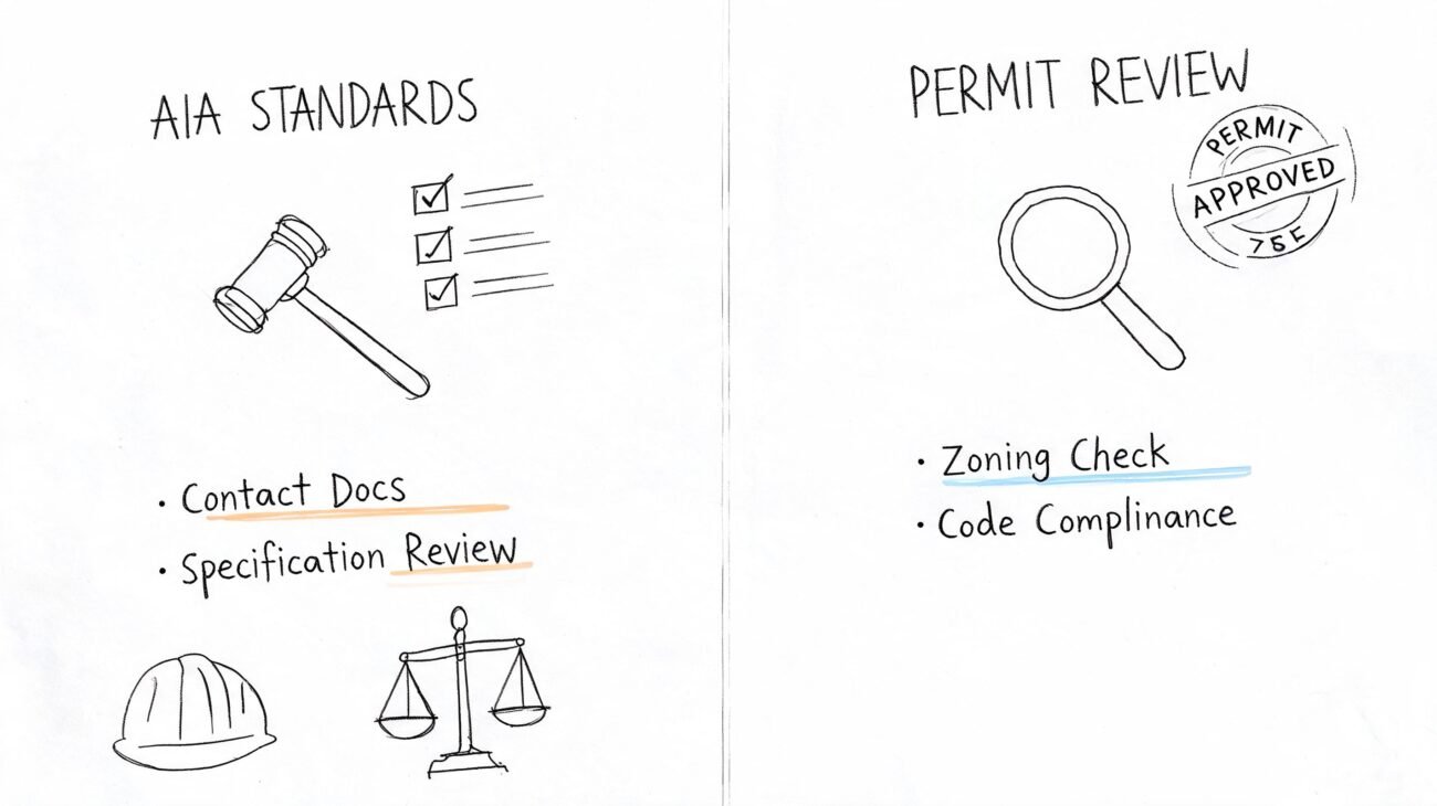
The Permit Correction You Can't Ignore
A typical correction reads like this: wall assembly not fully identified, evaluation report reference missing, structural design not clearly tied to the system, opening detail incomplete. None of those comments are dramatic on their own. Together, they stop progress.
The most common trigger is simple. The ICF wall went into the set as a generic insulated concrete wall, often because the project started from a standard template. That decision hides the scope gap. The wall isn't documented as a proprietary assembly, the engineer hasn't clearly stamped the load-bearing wall design for that assembly, and the window buck condition isn't shown where the reviewer expects it.
Practical rule: If the permit reviewer has to infer how the ICF wall is built, the set isn't ready.
That's the difference with concrete insulated forms. The problem usually isn't design intent. It's that the digital deliverable doesn't prove the team has coordinated the wall system, the openings, and the code path with enough precision to approve it.
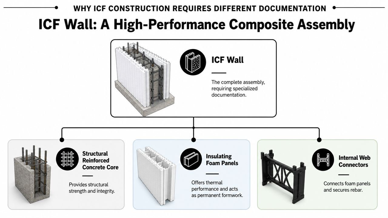
Why ICF Construction Requires Different Documentation
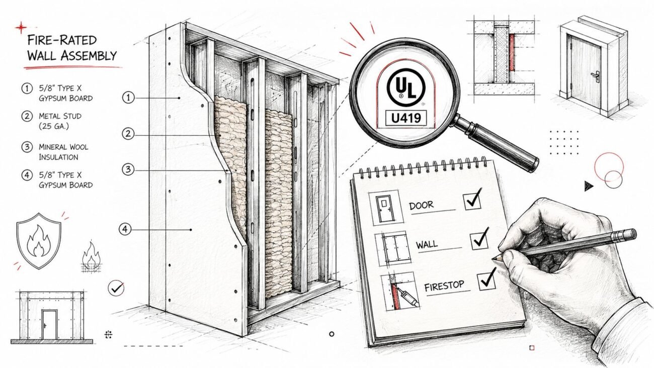
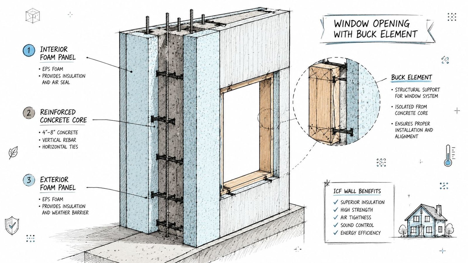
An ICF wall isn't one material. It's a composite assembly made of rigid foam forms that stay in place after the concrete pour, creating permanent insulated shuttering around reinforced concrete. That continuous insulation is one reason ICF wall assemblies reduce thermal bridging compared with conventional framed walls, as described in Building America guidance on insulated concrete forms.
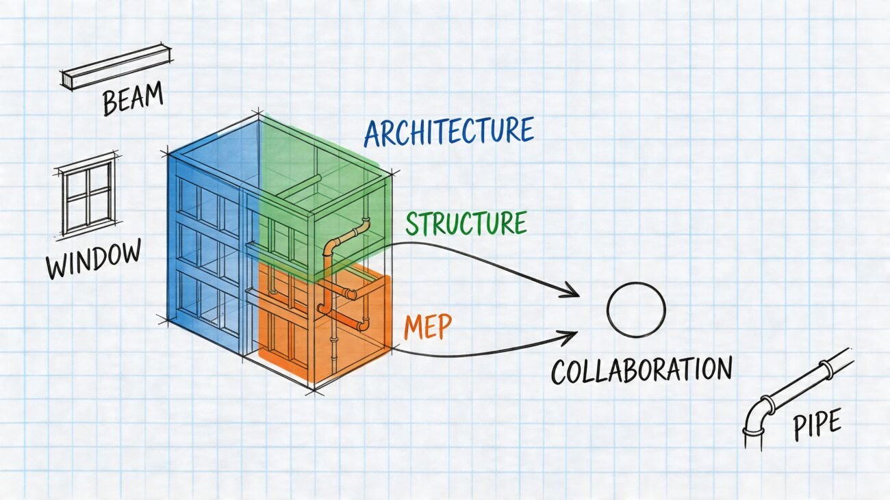
The model has to separate structure from insulation
In practice, the concrete core carries the structural job. The foam faces handle the insulation layer and affect finish dimensions, opening depth, and attachment conditions. If the model collapses that into one generic wall type, the documentation starts drifting immediately.
The first problem is geometry. A wall shown as a simple concrete assembly won't correctly communicate interior and exterior face conditions. That affects rough opening depth, trim returns, cladding attachment, and how sections read at a glance. The second problem is responsibility. The permit set has to distinguish the structural concrete core from the insulating foam faces, not present the wall as a single homogeneous element.
Mature system, higher expectation
This isn't a new product category that reviewers are still figuring out. The first North American foam ICF patent was filed by Werner Gregori in 1966 for a block measuring 16 inches high by 48 inches long, according to this history of ICF development. That matters because plan reviewers, engineers, and specialty installers already expect established documentation discipline around the system.
For architects who have worked with other panelized envelope systems, the documentation mindset is closer to structural insulated panel coordination than to a generic wall tag. The assembly has to be named, layered, and tied to the manufacturer's approved parameters. If that relationship isn't visible in the model and on the sheet, the set looks under-coordinated even when the design itself is sound.
What the Permit Set Must Show for ICF Walls
Permit reviewers don't need marketing language about performance. They need a set that identifies the exact system, shows who engineered it, and resolves the opening conditions that usually create questions.
Four items that can't stay implied
Start with the manufacturer and the evaluation report. The specific ICF product has to be named, and the ICC-ES evaluation report number needs to appear in the notes or wall schedule. That report is what anchors the permitted use of the system. If the drawings don't identify it, the reviewer has no clean path to verify what's being submitted.
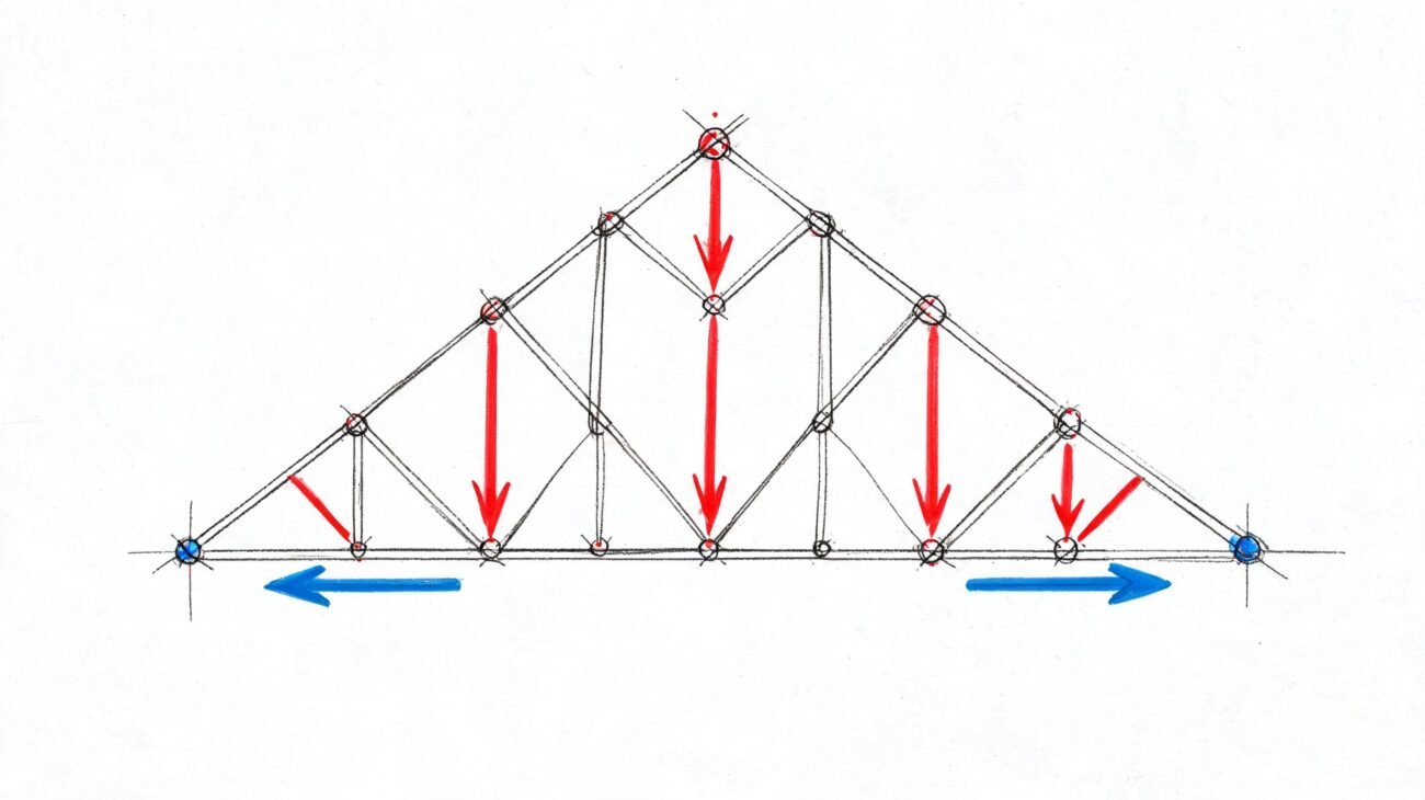
Next is the structural design. Load-bearing ICF walls require the engineer of record to design the concrete core, including reinforcing size, spacing, and lap locations. If that information sits in disconnected structural notes without a clear tie to the architectural wall type, reviewers often treat it as incomplete coordination.
Then there's the wall schedule itself. Many sets still appear generic in this regard. The schedule should show the full insulated concrete form wall assembly as layered construction, not a single wall fill. A strong office standard for wall type documentation makes this easier because the team can audit the wall family against the sheet legend before issue.
Openings are where weak sets get exposed
Window and door openings need a buck detail. That can be dimensional lumber or a proprietary buck system, but the set has to show the material, the rough opening logic, and how the buck integrates with the wall and weather barrier.
If the opening detail only shows a window in a thick wall, the reviewer still doesn't know how the rough opening is formed.
A reliable permit package for ICF walls should show, at minimum:
- System identification: Manufacturer name and ICC-ES report reference on the drawings.
- Engineered concrete core: Reinforcing layout, laps, and any lintel conditions under the structural stamp.
- Layered wall schedule: Exterior foam, concrete core, interior foam, plus applied finishes where relevant.
- Opening formation: Buck type, dimensions, fastening approach, and integration with flashing or WRB.
That level of specificity prevents the two most expensive assumptions in construction documents: “the installer will know” and “the reviewer will accept it.”
Modeling ICF Walls Correctly in Revit
A good permit set starts in the model. If the wall is wrong in Revit, the details, sections, schedules, and openings usually inherit the same problem.
Build the wall as a compound assembly
For insulated concrete forms Revit workflows, the base move is a compound wall type that mirrors the actual assembly. Model separate layers for exterior foam, concrete core, and interior foam. Assign the structural function to the concrete layer and thermal or air function to the foam layers.
That setup does more than make sections look better. It affects how joins clean up, how inserts cut the wall, and how structural elements reference the assembly. If the concrete core isn't treated as the structural layer, the model can produce misleading intersections and poor documentation at slabs, roofs, and bearing points.
A quick QA table helps catch bad wall definitions early:
| Model item | What should happen |
|---|---|
| Wall type name | Identifies it as an ICF assembly, not generic concrete |
| Layer structure | Separate foam and concrete layers are visible |
| Structural function | Assigned to the concrete core |
| Schedules and tags | Report the assembly in a way that matches sheet legends |
Don't use standard window families and hope for the best
Openings are where generic content breaks. An ICF wall is deeper than a typical framed wall, so a standard residential window family often sits incorrectly, cuts the wrong reveal, or produces sections that don't communicate the installation condition.
Use window and door families with adjustable depth logic, or build project-specific content for ICF applications. The opening should show the correct reveal relative to the full wall thickness, not just the concrete core. Then model the buck as a separate element or nested family so it appears in plan, section, and detail views.
That approach pays off in coordination. The framer, installer, and reviewer can all read the same condition. It also helps quantity takeoff and detail consistency because the buck is no longer hidden inside drafting lines.
Field note: If the buck only exists in a 2D detail and not in the model, someone will eventually ask whether the opening dimensions are to foam, to buck, or to concrete.
Irregular geometry needs its own QA pass
Straight ICF walls are manageable. Angles, curves, T-walls, and custom geometry are where teams lose time. Independent training material notes that angled components are typically less than 5% of the wall area, yet they can drive a disproportionate share of coordination effort and field risk, as shown in this angle-wall ICF training reference.
That's exactly why the ICF BIM model can't stop at “close enough” geometry. At non-orthogonal conditions, check three things:
- Concrete core continuity across every corner or angle.
- Opening orientation so bucks, reveals, and head conditions still read correctly.
- Bracing and constructability cues in enlarged views where the assembly becomes harder to interpret.
For custom plans, this is usually the hardest part of the job. The tricky geometry is a small share of area, but it's where RFIs multiply if the model hasn't resolved the condition before issue.
Thermal and Energy Code Documentation for ICF
ICF projects often underperform in permit review for a frustrating reason. The wall is capable of strong energy performance, but the submittal doesn't document it in the correct category.
Continuous insulation only helps if the paperwork matches the wall
ICF walls are recognized for insulation without thermal bridging, along with air sealing and structural strength, in Building America guidance summarized through this ICF history reference. The same source also notes that U.S. Department of Housing and Urban Development figures cite 20% to 25% annual heating and cooling savings for homeowners and businesses when ICF walls are used. That benefit only matters in permitting if the energy model and compliance forms classify the wall correctly.
For code compliance, the wall assembly needs to be documented as a mass wall with continuous insulation. If the compliance input gets entered under wood frame or steel frame logic, the result won't reflect the assembly being built.
The handoff between architecture and energy compliance has to be explicit
Production teams need a checkpoint, not just a note. The wall type in the model, the wall schedule in the set, and the envelope input in the compliance submission should all describe the same assembly.
A simple review sequence works:
- Confirm assembly naming: The wall in the model and on the sheet should clearly identify it as ICF.
- Confirm thermal layer intent: The foam faces should be represented as continuous insulation in the assembly notes.
- Confirm compliance category: Enter the wall under the proper mass wall path in the energy documentation.
- Confirm consultant alignment: The person preparing energy code compliance documentation should be working from the same wall definition used in the permit set.
This isn't a paperwork footnote. It's a coordination issue. If the architecture team models one thing and the compliance submission classifies another, the project can end up solving an energy problem that only exists because the wall was entered incorrectly.
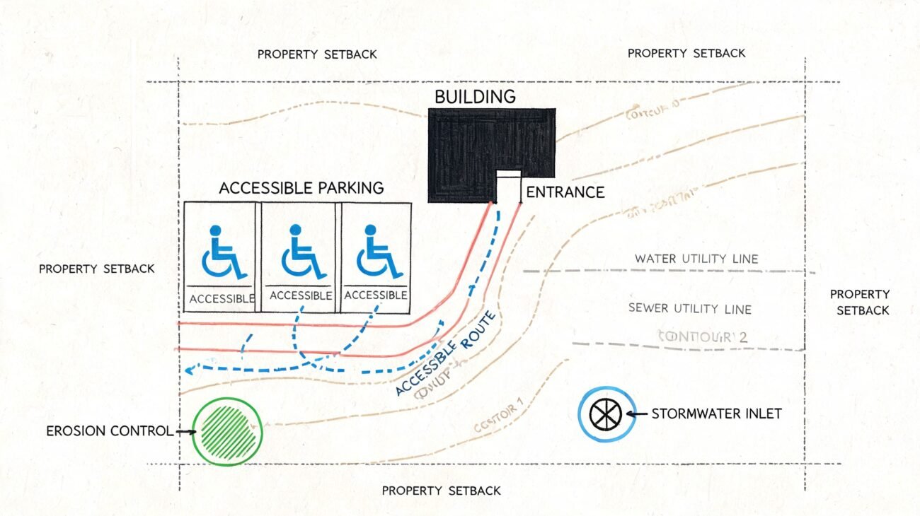
ICF Foundation Wall Documentation
Foundation work is where ICF detailing gets more exposed to jurisdictional review. Above grade, some missing information can limp along until an RFI. Below grade, missing information tends to trigger direct permit comments because moisture control and pest pathways are code and liability issues.
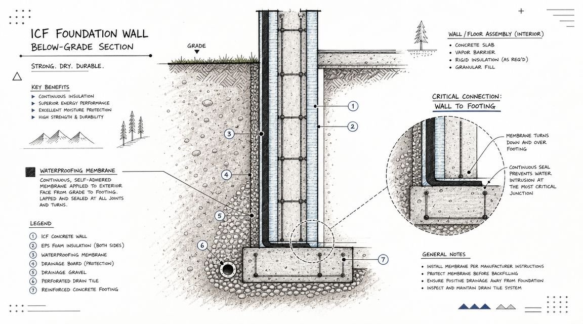
Show the wall below grade as a protected assembly
The exterior foam face needs a waterproofing strategy and physical protection before backfill. If the foundation detail stops at “dampproofing by others” or shows soil directly against an unfinished foam face, the set looks incomplete.
A clean detail should show the waterproofing layer, the protection board or drainage mat, and the transition to the above-grade weather-resistive barrier. That transition matters because it tells the reviewer the team has thought through continuity, not just isolated products.
The drawing set should also communicate that installation sequencing has been considered. That includes the relationship between wall, membrane, drainage layer, and final grade. Without that, the permit set leaves too much to field interpretation.
Don't treat termite protection as regional trivia
In termite-active areas, concealed pathways are a real review concern at ICF foundations. The foam face can create a hidden route from soil to the wood structure above if the top-of-wall condition isn't detailed correctly.
That's why the permit set should show a termite barrier strategy at the ICF foundation and sill plate condition where required by jurisdiction. Depending on local requirements, that may be a metal termite shield or an inspectable gap that keeps the path visible.
Omit that detail in a warm-climate jurisdiction and the reviewer may assume the team copied a cold-region standard into the set without adjusting for local code expectations.
A solid ICF construction documents permit package doesn't bury this in specifications. It places the detail where the reviewer can see it in the wall section or enlarged foundation condition.
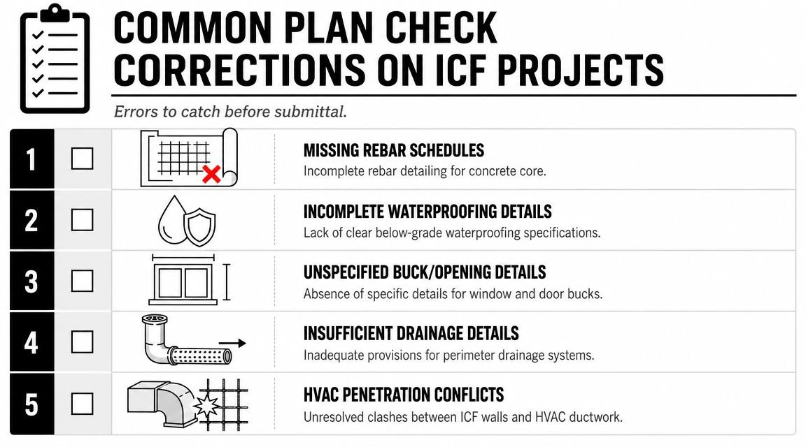
Common Plan Check Corrections on ICF Projects
The fastest way to improve consistency is to stop treating ICF corrections as one-off reviewer preferences. They're repeatable failures, which means they belong on a repeatable QA checklist.
The pre-submittal audit that catches most of them
Run this review before the issue set leaves production:
- Evaluation report reference present: The manufacturer and ICC-ES report number appear in notes or the wall legend.
- Structural scope aligned: Every load-bearing ICF wall is covered in the structural design and stamp.
- Buck detail included: Window and door opening details show how the rough opening is formed and fastened.
- Wall thickness checked: The model and schedules match the actual system dimensions used on the project.
- Energy category verified: The compliance submission classifies the wall under the correct path.
- Below-grade protection shown: Waterproofing and protection at foundation walls appear in the details.
- Termite condition resolved: Required barrier or inspection detail is included for the jurisdiction.
Turn common failures into office standards
The firms that handle these projects well don't rely on memory. They build standards. The general notes template carries the proprietary system reference. The Revit template includes reviewed ICF wall types. The detail library includes a vetted buck condition and foundation transition. The permit checklist forces one last pass on energy category and structural coverage.
That's what production maturity looks like. Not more effort, just fewer assumptions.
A well-run office also knows where to spend attention. The straight walls usually aren't the problem. The odd geometry, the opening conditions, the below-grade transitions, and the consultant handoffs are where review comments are born. If your QA process hunts those areas first, you'll prevent more kickbacks than any amount of broad “document better” advice ever will.
From Model to Site with Confidence
Concrete insulated forms reward teams that document them as systems, not approximations. When the model shows the actual assembly, the permit set identifies the proprietary basis of design, and the details resolve openings and foundations clearly, review gets smoother and field questions drop.
That's the practical payoff. Better predictability, fewer RFIs, and less margin erosion from preventable revisions. The projects that go well aren't the ones with the fanciest wall renderings. They're the ones where the BIM model, permit set, and consultant inputs all describe the same wall.
If your team needs help clearing production bottlenecks on ICF work, BIM Heroes can support Revit production, model cleanup, wall type setup, and permit-ready documentation through its architectural production services. Reach out if a checklist, template, or second-pass QA framework would help your next ICF set go out cleaner.